
SPFL® Industrial Fasteners
Fastener requirements should be specified by product type, material/grade, size, thread, standard and quantity. Use the enquiry process to provide your exact requirement or drawing.
Fastener Subcategories
- BoltsHex, Allen/socket-head, U, flange, carriage, L, J, T, eye, dome-head, anti-theft and stud bolts.
- NutsHex, lock, Nylock, dome, wing, eye, square, heavy hex, weld, flange, coupling, castle and rivet nuts.
- WashersPlain, spring, shim, tab, taper, star and square washers.
- ScrewsMachine, slotted, Phillips, countersunk, self-tapping, wood/coach, socket-head, Allen cap and grub screws.
- Threaded RodsFully threaded rods and half-threaded studs.
- CirclipsExternal, internal and E-type circlips. Ask us about your required size.
- AnchorsAnchor bolts and anchor fasteners; share the required type and drawing for confirmation.
- Rivets & PinsSolid/pop rivets, dowel pins and cotter/split pins.
Technical Selection
Capture material/grade, nominal diameter, length, thread form/pitch, finish, standard and quantity as applicable to the selected fastener.
Enquiry Documentation
Customers can share a drawing, specification or purchase requirement so dimensions and applicable standards can be reviewed.
TECHNICAL REFERENCE
Bolt, Screw, Stud & Anchor Specifications
The tables below are transcribed from the dimensional reference supplied for this catalogue. Unless otherwise stated, dimensions are in millimetres (mm). The source document marks all information as strictly informative; confirm the required dimensions, material, standard and availability for each enquiry.
Bolts & anchors
DIN 186 – Tee-head bolts with square head
| d₁ | b | k | s |
|---|---|---|---|
| M6 | 18 | 4.5 | 6 |
| M8 | 22 | 5.5 | 8 |
| M10 | 26 | 7 | 10 |
| M12 | 30 | 8 | 12 |
| M16 | 38 | 10.5 | 16 |
| M20 | 46 | 13 | 20 |
U-bolt standard
| Nominal Pipe Size (Imperial) | Nominal Pipe Size (Metric) | A | A1 | C | Thread Size |
|---|---|---|---|---|---|
| 1/2 | 15 | 12 | 48 | 29 | M6 |
| 3/4 | 20 | 15 | 53 | 35 | M6 |
| 1 | 25 | 20 | 60 | 42 | M6 |
| 1 1/4 | 32 | 25 | 70 | 52 | M8 |
| 1 1/2 | 40 | 30 | 75 | 60 | M8 |
| 2 | 50 | 35 | 85 | 72 | M8 |
| 2 1/2 | 65 | 40 | 100 | 88 | M10 |
| 3 | 80 | 40 | 115 | 103 | M10 |
| 4 | 100 | 40 | 140 | 130 | M12 |
| 5 | 125 | 40 | 165 | 153 | M12 |
| 6 | 150 | 50 | 195 | 182 | M12 |
| 7 | 175 | 50 | 225 | 209 | M12 |
| 8 | 200 | 50 | 245 | 240 | M16 |
| 9 | 225 | 50 | 275 | 264 | M16 |
| 10 | 250 | 50 | 315 | 293 | M16 |
| 12 | 300 | 50 | 360 | 342 | M16 |
| 14 | 350 | 85 | 395 | 378 | M16 |
| 16 | 400 | 85 | 485 | 428 | M16 |
| 18 | 450 | 85 | 540 | 478 | M16 |
| 20 | 500 | 85 | 595 | 528 | M16 |
DIN 188 – Tee-head bolts with double nip
| d | b | k | m | n |
|---|---|---|---|---|
| M8 | 22 | 5.5 | 18 | 8 |
| M10 | 26 | 7 | 21 | 10 |
| M12 | 30 | 8 | 26 | 12 |
| M16 | 38 | 10.5 | 30 | 16 |
| M24 | 54 | 15 | 43 | 24 |
DIN 444 – Eye bolts
| d | d₁ | d₂ | b to 125 | b to 200 |
|---|---|---|---|---|
| M5 | 12 | 5 | 16 | |
| M6 | 14 | 6 | 18 | |
| M8 | 18 | 8 | 22 | 28 |
| M10 | 20 | 10 | 26 | 32 |
| M12 | 25 | 12 | 30 | 36 |
| M16 | 32 | 16 | 38 | 44 |
| M20 | 40 | 18 | 46 | 52 |
DIN 525 – Weld studs with hexagon nuts
| d₁ | l | b |
|---|---|---|
| M6 | 130 | 35 |
| M8 | 140 | 40 |
| M10 | 150 | 45 |
| M12 | 170 | 55 |
| M14 | 180 | 60 |
| M16 | 190 | 65 |
| M18 | 200 | 70 |
| M20 | 210 | 75 |
| M22 | 220 | 80 |
| M24 | 230 | 85 |
| M27 | 250 | 90 |
| M30 | 270 | 105 |
| M33 | 290 | 115 |
| M36 | 310 | 125 |
DIN 529 – Anchor bolts (stone bolts)
| d₁ | b | a approx. |
|---|---|---|
| M8 | 20 | 24 |
| M10 | 25 | 30 |
| M12 | 30 | 36 |
| M16 | 40 | 48 |
| M20 | 50 | 60 |
| M24 | 60 | 75 |
| M30 | 75 | 95 |
DIN 558 – Fully threaded machine bolts
| d₁ | s | e | k |
|---|---|---|---|
| M6 | 10 | 10.89 | 4 |
| M8 | 13 | 14.2 | 5.3 |
| M10 | 17 | 18.72 | 6.4 |
| M12 | 19 | 20.88 | 7.5 |
| M16 | 24 | 26.17 | 10 |
| M20 | 30 | 32.95 | 12.5 |
DIN 580 – Lifting eye bolts
| d₁ | h | b | d₂ | d₃ | d₄ | k |
|---|---|---|---|---|---|---|
| M6 | 27.5 | 12 | 27 | 19 | 14 | 6.5 |
| M8 | 36 | 13 | 36 | 20 | 20 | 8 |
| M10 | 45 | 17 | 45 | 25 | 25 | 10 |
| M12 | 53 | 20.5 | 54 | 30 | 30 | 12 |
| M14 | 62 | 27 | 63 | 35 | 35 | 14 |
| M16 | 62 | 27 | 63 | 35 | 35 | 14 |
| M20 | 71 | 30 | 72 | 40 | 40 | 16 |
| M22 | 90 | 36 | 90 | 50 | 50 | 20 |
| M24 | 90 | 36 | 90 | 50 | 50 | 20 |
| M27 | 109 | 45 | 108 | 65 | 60 | 24 |
| M30 | 109 | 45 | 108 | 65 | 60 | 24 |
| M33 | 128 | 54 | 126 | 75 | 70 | 28 |
| M36 | 128 | 54 | 126 | 75 | 70 | 28 |
| M42 | 147 | 63 | 144 | 85 | 80 | 32 |
| M45 | 168 | 68 | 166 | 100 | 90 | 38 |
| M48 | 168 | 68 | 166 | 100 | 90 | 38 |
| M52 | 187 | 78 | 184 | 110 | 100 | 42 |
| M56 | 187 | 78 | 184 | 110 | 100 | 42 |
| M64 | 208 | 90 | 206 | 120 | 110 | 48 |
| M72 | 260 | 100 | 260 | 150 | 140 | 60 |
| M80 | 298 | 112 | 296 | 170 | 160 | 68 |
DIN 609 – Hex fitting bolts with long threaded portion
| d | k | e | s | b = to 50 | b = to 150 | b = to 200 |
|---|---|---|---|---|---|---|
| M8 | 5.3 | 14.38 | 13 | 14.5 | 16.5 | 21.5 |
| M10 | 6.4 | 17.77 | 16 | 17.5 | 19.5 | 24.5 |
| M12 | 7.5 | 19.85 | 18 | 20.5 | 22.5 | 27.5 |
| M14 | 8.8 | 22.78 | 21 | 22 | 24 | 29 |
| M16 | 10 | 26.17 | 24 | 25 | 27 | 32 |
| M20 | 12.5 | 32.95 | 30 | 28.5 | 30.5 | 35.5 |
| M24 | 15 | 39.55 | 36 | – | 36.5 | 41.5 |
| M30 | 19 | 50.85 | 46 | – | 43 | 48 |
DIN 610 – Hex fitting bolts with short threaded portion
| d | k | e | s max. | b = to 50 | b = to 150 | b = to 200 |
|---|---|---|---|---|---|---|
| M8 | 5.3 | 14.38 | 13 | 11.5 | 13.5 | 18.5 |
| M10 | 6.4 | 17.77 | 16 | 13.5 | 15.5 | 20.5 |
| M12 | 7.5 | 19.85 | 18 | 15.5 | 17.5 | 22.5 |
| M14 | 8.8 | 22.78 | 21 | 17 | 19 | 24 |
| M16 | 10 | 26.17 | 24 | 19 | 21 | 26 |
| M20 | 12.5 | 32.95 | 30 | 22.5 | 24.5 | 29.5 |
| M24 | 15 | 39.55 | 36 | 26.5 | 28.5 | 33.5 |
| M30 | 19 | 50.85 | 46 | – | 34 | 39 |
DIN 6914 – Hex bolts for high-strength structural bolting
| d | s | e | k | b |
|---|---|---|---|---|
| M12 | 22 | 23.91 | 8 | 21 |
| M16 | 27 | 29.56 | 10 | 26 |
| M20 | 32 | 35.03 | 13 | 31 |
| M22 | 36 | 39.55 | 14 | 32 |
| M24 | 41 | 45.2 | 15 | 34 |
| M27 | 46 | 50.85 | 17 | 37 |
| M30 | 50 | 55.37 | 19 | 40 |
| M36 | 60 | 66.44 | 23 | 48 |
Screws
DIN 316 – Wing screws
| d | h | e | d₂ |
|---|---|---|---|
| M4 | 8.5 | 18 | 6 |
| M5 | 11 | 24 | 8 |
| M6 | 15 | 30 | 10 |
| M8 | 18 | 36 | 13 |
| M10 | 23 | 48 | 17 |
| M12 | 31 | 62 | 20 |
| M16 | 35 | 70 | 26 |
DIN 427 – Slotted headless screws
| d₁ | b | n | t min. |
|---|---|---|---|
| M3 | 3.6 | 0.4 | 0.8 |
| M4 | 4.8 | 0.6 | 1.12 |
| M5 | 6 | 0.8 | 1.28 |
| M6 | 7.2 | 1 | 1.6 |
| M8 | 9.6 | 1.2 | 2 |
| M10 | 12 | 1.6 | 2.4 |
| M12 | 14 | 2 | 3.7 |
| M16 | 18 | 2.5 | 4.2 |
DIN 464 – Knurled thumb screws
| d₁ | d k | d max. s | h | k max. |
|---|---|---|---|---|
| M3 | 12 | 6 | 7.5 | 2.5 |
| M4 | 16 | 8 | 9.5 | 3.5 |
| M5 | 20 | 10 | 11.5 | 4 |
| M6 | 24 | 12 | 15 | 5 |
| M8 | 30 | 16 | 18 | 6 |
| M10 | 36 | 20 | 23 | 8 |
DIN 653 – Flat knurled thumb screws
| d | d k | k |
|---|---|---|
| M3 | 12 | 2.5 |
| M4 | 16 | 3.5 |
| M5 | 20 | 4 |
| M6 | 24 | 5 |
| M8 | 30 | 6 |
| M10 | 36 | 8 |
DIN 931 – Hexagon head screws, partially threaded
| d₁ | b to 125 | b to 200 | b over 200 | k | e | s |
|---|---|---|---|---|---|---|
| M4 | 14 | – | – | 2.8 | 7.66 | 7 |
| M5 | 16 | – | – | 3.5 | 8.79 | 8 |
| M6 | 18 | 24 | – | 4 | 11.05 | 10 |
| M8 | 22 | 28 | – | 5.3 | 14.38 | 13 |
| M10 | 26 | 32 | 45 | 6.4 | 18.9 | 17 |
| M12 | 30 | 36 | 49 | 7.5 | 21.1 | 19 |
| M14 | 34 | 40 | 53 | 8.8 | 24.49 | 22 |
| M16 | 38 | 44 | 57 | 10 | 26.75 | 24 |
| M18 | 42 | 48 | 61 | 11.5 | 30.14 | 27 |
| M20 | 46 | 52 | 65 | 12.5 | 33.53 | 30 |
| M22 | 50 | 56 | 69 | 14 | 35.72 | 32 |
| M24 | 54 | 60 | 73 | 15 | 39.98 | 36 |
| M27 | 60 | 66 | 79 | 17 | 45.2 | 41 |
| M30 | 66 | 72 | 85 | 18.7 | 50.85 | 46 |
| M33 | 72 | 78 | 91 | 21 | 55.37 | 50 |
| M36 | 78 | 84 | 97 | 22.5 | 60.79 | 55 |
| M42 | 90 | 96 | 109 | 26 | 71.3 | 65 |
| M45 | 96 | 102 | 115 | 28 | 76.95 | 70 |
| M48 | 102 | 108 | 121 | 30 | 82.60 | 75 |
DIN 933 – Hexagon head screws, fully threaded
| d₁ | k | e | s |
|---|---|---|---|
| M3 | 2 | 6.01 | 5.5 |
| M4 | 2.8 | 7.66 | 7 |
| M5 | 3.5 | 8.79 | 8 |
| M6 | 4 | 11.05 | 10 |
| M8 | 5.3 | 14.38 | 13 |
| M10 | 6.4 | 18.9 | 17 |
| M12 | 7.5 | 21.1 | 19 |
| M14 | 8.8 | 24.49 | 22 |
| M16 | 10 | 26.75 | 24 |
| M18 | 11.5 | 30.14 | 27 |
| M20 | 12.5 | 33.53 | 30 |
| M22 | 14 | 35.72 | 32 |
| M24 | 15 | 39.98 | 36 |
| M27 | 17 | 45.2 | 41 |
| M30 | 18.7 | 50.85 | 46 |
| M33 | 21 | 55.37 | 50 |
| M36 | 22.5 | 60.79 | 55 |
| M42 | 26 | 71.3 | 65 |
| M48 | 30 | 82.6 | 75 |
DIN 960 – Hex screws, metric fine thread, part thread
| d₁ | s | e | k | b= to 125 | b= to 150 | b= to 200 |
|---|---|---|---|---|---|---|
| M8 x 1 | 13 | 14.38 | 5.3 | 22 | 28 | |
| M10 x 1 | 17 | 18.9 | 6.4 | 26 | 32 | |
| M10 x 1.25 | 17 | 18.9 | 6.4 | 26 | 32 | |
| M12 x 1.25 | 19 | 21.1 | 7.5 | 30 | 36 | |
| M12 x 1.5 | 19 | 21.1 | 7.5 | 30 | 36 | |
| M14 x 1.5 | 22 | 24.49 | 8.8 | 34 | 40 | |
| M16 x 1.5 | 24 | 26.75 | 10 | 38 | 44 | |
| M18 x 1.5 | 27 | 30.14 | 11.5 | 42 | 48 | |
| M20 x 1.5 | 30 | 33.53 | 12.5 | 46 | 52 | |
| M20 x 2 | 30 | 33.53 | 12.5 | 46 | 52 | |
| M24 x 2 | 36 | 39.98 | 15 | 54 | 60 |
DIN 961 – Hex screws, metric fine thread, full thread
| d₁ | s | e | k |
|---|---|---|---|
| M8 | 13 | 14.38 | 5.3 |
| M10 | 17 | 18.9 | 6.4 |
| M12 | 19 | 21.1 | 7.5 |
| M14 | 22 | 24.49 | 8.8 |
| M16 | 24 | 26.75 | 10 |
| M18 | 27 | 30.14 | 11.5 |
| M20 | 30 | 33.53 | 12.5 |
| M22 | 32 | 35.72 | 14 |
| M24 | 36 | 39.98 | 15 |
| M27 | 41 | 45.63 | 17 |
| M30 | 46 | 51.28 | 19 |
| M33 | 50 | 55.8 | 21 |
| M36 | 55 | 61.31 | 23 |
| M39 | 60 | 66.96 | 25 |
| M42 | 65 | 72.61 | 26 |
| M45 | 70 | 78.26 | 28 |
| M48 | 75 | 83.91 | 30 |
| M52 | 80 | 89.56 | 33 |
Studs & threaded rods
DIN 835 – Studs, tap end – 2d
| d₁ | b | e | x |
|---|---|---|---|
| M6 | 18 | 12 | 2.5 |
| M8 | 22 | 16 | 3.2 |
| M10 | 26 | 20 | 3.8 |
| M12 | 30 | 24 | 4.3 |
| M16 | 38 | 32 |
DIN 939 – Studs, tap end – 1.25d
| d₁ | b | e |
|---|---|---|
| M4 | 14 | 5 |
| M5 | 16 | 6.5 |
| M6 | 18 | 7.5 |
| M7 | 20 | 9 |
| M8 | 22 | 10 |
| M10 | 26 | 12 |
| M12 | 30 | 15 |
| M14 | 34 | 18 |
| M16 | 38 | 20 |
| M18 | 42 | 22 |
| M20 | 46 | 25 |
| M22 | 50 | 28 |
| M24 | 54 | 30 |
| M27 | 60 | 35 |
| M30 | 66 | 38 |
| M33 | 72 | 42 |
| M36 | 78 | 45 |
| M39 | 84 | 50 |
| M42 | 90 | 52 |
| M45 | 96 | 58 |
| M48 | 102 | 60 |
| M52 | 110 | 65 |
DIN 976 – Stud bolt, full thread
| d | Pitch | Length |
|---|---|---|
| M-4 | 0.7 | 10 mm to 3 m |
| M-5 | 0.8 | 10 mm to 3 m |
| M-6 | 1.0 | 12 mm to 3 m |
| M-8 | 1.25 | 12 mm to 3 m |
| M-10 | 1.5 | 15 mm to 6 m |
| M-12 | 1.75 | 20 mm to 6 m |
| M-14 | 2.0 | 30 mm to 6 m |
| M-16 | 2.0 | 35 mm to 6 m |
| M-18 | 2.5 | 50 mm to 6 m |
| M-20 | 2.5 | 50 mm to 6 m |
| M-22 | 2.5 | 50 mm to 6 m |
| M-24 | 3.0 | 60 mm to 6 m |
| M-27 | 3.0 | 100 mm to 6 m |
| M-30 | 3.5 | 100 mm to 6 m |
| M-33 | 3.5 | 100 mm to 6 m |
| M-36 | 4.0 | 150 mm to 6 m |
| M-39 | 4.0 | 200 mm to 6 m |
| M-42 | 4.5 | 200 mm to 5 m |
| M-45 | 4.5 | 250 mm to 5 m |
| M-48 | 5.0 | 300 mm to 5 m |
| M-52 | 5.0 | 350 mm to 5 m |
| M-56 | 5.5 | 350 mm to 5 m |
| M-60 | 5.5 | 350 mm to 5 m |
TECHNICAL REFERENCE
Nut Tables
Dimensions are shown in millimetres (mm). The supplied reference describes the information as strictly informative; confirm the applicable standard and dimensions for each enquiry.
Nut dimensional tables
DIN 193 Flange Nuts Specifications
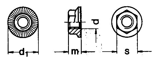
| d | d1 | s | m |
|---|---|---|---|
| M5 | 11.2 | 8 | 4.3 |
| M6 | 14.2 | 10 | 5.5 |
| M8 | 18.2 | 13 | 7 |
| M10 | 21 | 15 | 8.5 |
| M12 | 24 | 17 | 10 |
| M16 | 31 | 22 | 14 |
DIN 196 Flange Nuts Specifications
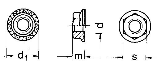
| d | d1 | s | m |
|---|---|---|---|
| M5 | 11.2 | 8 | 4.3 |
| M6 | 14.25 | 10 | 5.5 |
| M8 | 18.25 | 13 | 7 |
| M10 | 21 | 15 | 7.9 |
| M12 | 24 | 17 | 8.7 |
| M16 | 31 | 22 | 11.5 |
DIN 315 – Wing Nuts Specifications
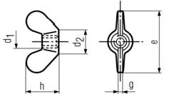
Catalogue reference range: M4 to M24
| d1 | d2 | e | g | h |
|---|---|---|---|---|
| M4 | 6 | 18 | 1.7 | 8.5 |
| M5 | 8 | 24 | 2.3 | 11 |
| M6 | 10 | 30 | 2.7 | 15 |
| M8 | 13 | 36 | 3.6 | 18 |
| M10 | 17 | 48 | 4.6 | 23 |
| M12 | 20 | 62 | 5.6 | 31 |
| M16 | 26 | 70 | 6.5 | 35 |
| M20 | 32 | 86 | 7 | 44 |
| M24 | 41 | 106 | 8.6 | 53.5 |
DIN 431 – Lock Nut, Hexagonal Specifications
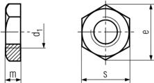
| d1 | s | e | m min. |
|---|---|---|---|
| G 1/8 | 19 | 20.88 | 6 |
| G 1/4 | 22 | 23.91 | 6 |
| G 3/8 | 27 | 29.56 | 7 |
| G 1/2 | 32 | 35.03 | 8 |
| G 5/8 | 32 | 35.04 | 8 |
| G 3/4 | 36 | 39.55 | 9 |
| G 1 | 46 | 50.85 | 10 |
| G 1-1/8 | 50 | 55.37 | 10 |
| G 1-1/4 | 55 | 60.79 | 11 |
| G 1-1/2 | 60 | 66.44 | 12 |
| G 1-3/4 | 70 | 76.93 | 13 |
| G 2 | 75 | 82.80 | 13 |
DIN 439 – Hexagon Nuts – 0,5d Unchamfered Specifications
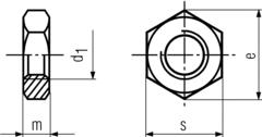
Catalogue reference range: M5 to M56
| d1 | s | e | m |
|---|---|---|---|
| M2 | 4 | 4.32 | 1.2 |
| M3 | 5.5 | 6.01 | 1.8 |
| M4 | 7 | 7.66 | 2.2 |
| M5 | 8 | 8.79 | 2.7 |
| M6 | 10 | 11.05 | 3.2 |
| M8 | 13 | 14.38 | 4 |
| M10 | 17 | 18.9 | 5 |
| M12 | 19 | 21.1 | 6 |
| M14 | 22 | 24.49 | 7 |
| M16 | 24 | 26.75 | 8 |
| M18 | 27 | 29.56 | 9 |
| M20 | 30 | 32.95 | 10 |
| M22 | 32 | 35.03 | 11 |
| M24 | 36 | 39.55 | 12 |
| M27 | 41 | 45.2 | 13.5 |
| M30 | 46 | 50.85 | 15 |
| M33 | 50 | 55.37 | 16.5 |
| M36 | 55 | 60.79 | 18 |
DIN 466 – Knurled Nuts, Full Specifications
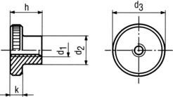
| d1 | d3 | d2 max. | h max. | k max. |
|---|---|---|---|---|
| M3 | 12 | 6 | 7.5 | 2.5 |
| M4 | 16 | 8 | 9.5 | 3.5 |
| M5 | 20 | 10 | 11.5 | 4 |
| M6 | 24 | 12 | 15 | 5 |
| M8 | 30 | 16 | 18 | 6 |
| M10 | 36 | 20 | 23 | 8 |
DIN 467 – Knurled Nuts, Full Specifications
| d1 | d3 | d2 max. | h max. | k max |
|---|---|---|---|---|
| M3 | 12 | 6 | 3 | 2.5 |
| M4 | 16 | 8 | 4 | 3.5 |
| M5 | 20 | 10 | 5 | 4 |
| M6 | 24 | 12 | 6 | 5 |
| M8 | 30 | 16 | 8 | 6 |
| M10 | 36 | 20 | 10 | 8 |
DIN 555 – Hexagon Nuts – 0,8d Specifications
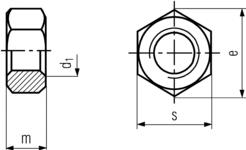
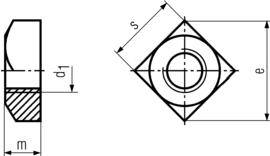
| d1 | s | e | m |
|---|---|---|---|
| M5 | 8 | 8.63 | 4 |
| M6 | 10 | 10.89 | 5 |
| M8 | 13 | 14.2 | 6.5 |
| M10 | 17 | 18.72 | 8 |
| M12 | 19 | 20.88 | 10 |
| M14 | 22 | 24.49 | 11 |
| M16 | 24 | 26.17 | 13 |
| M18 | 27 | 29.56 | 15 |
| M20 | 30 | 32.95 | 16 |
| M22 | 32 | 35.03 | 18 |
| M24 | 36 | 39.55 | 19 |
| M27 | 41 | 45.2 | 22 |
| M30 | 46 | 50.85 | 24 |
| M33 | 50 | 55.37 | 26 |
| M36 | 55 | 60.79 | 29 |
| M39 | 60 | 66.44 | 31 |
| M42 | 65 | 71.3 | 34 |
| M45 | 70 | 76.95 | 36 |
| M48 | 75 | 82.06 | 38 |
| M52 | 80 | 88.25 | 42 |
| M56 | 85 | 93.56 | 45 |
| M60 | 90 | 99.23 | 48 |
| M64 | 95 | 104.86 | 51 |
DIN 557 – Square Nuts Specifications
Catalogue reference range: M4 to M24
| d1 | s | e | m |
|---|---|---|---|
| M5 | 8 | 11.3 | 4 |
| M6 | 10 | 14.1 | 5 |
| M8 | 13 | 18.4 | 6.5 |
| M10 | 16 | 22.6 | 8 |
| M12 | 18 | 25.4 | 10 |
| M16 | 24 | 33.9 | 13 |
DIN 562 – Square Thin Nuts Specifications
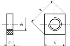
| d1 | s | e | m |
|---|---|---|---|
| M3 | 5.5 | 7 | 1.8 |
| M4 | 7 | 8.9 | 2.2 |
| M5 | 8 | 10.2 | 2.7 |
| M6 | 10 | 12.7 | 3.2 |
| M8 | 13 | 16.5 | 4 |
| M10 | 17 | 21.5 | 5 |
| M12 | 19 | 24 | 10 |
| M14 | 22 | 27.5 | 11 |
| M16 | 24 | 30.1 | 13 |
| M18 | 27 | 34 | 15 |
| M20 | 30 | 37.9 | 16 |
| M22 | 32 | 40.3 | 18 |
| M24 | 36 | 45.5 | 19 |
| M27 | 41 | 52 | 22 |
| M30 | 46 | 58.5 | 24 |
| M33 | 50 | 63.7 | 26 |
| M36 | 55 | 69.9 | 29 |
| M39 | 60 | 76.4 | 31 |
DIN 582 – Lifting Eye Nuts Specifications
Catalogue reference range: M6 to M36
| d1 | d2 | d3 | d4 | h | k |
|---|---|---|---|---|---|
| M6 | 28 | 16 | 17 | 36 | |
| M8 | 36 | 20 | 20 | 36 | 8 |
| M10 | 45 | 25 | 25 | 45 | 10 |
| M12 | 54 | 30 | 30 | 53 | 12 |
| M14 | 54 | 30 | 30 | 53 | 12 |
| M16 | 63 | 35 | 35 | 62 | 14 |
| M20 | 72 | 40 | 40 | 71 | 16 |
| M24 | 90 | 50 | 50 | 90 | 20 |
| M27 | 90 | 50 | 50 | 90 | 20 |
| M30 | 108 | 65 | 60 | 109 | 24 |
| M36 | 126 | 75 | 70 | 128 | 28 |
| M42 | 144 | 85 | 80 | 147 | 32 |
| M48 | 166 | 100 | 90 | 168 | 38 |
| M56 | 184 | 110 | 100 | 187 | 42 |
| M64 | 206 | 120 | 110 | 208 | 48 |
DIN 917 – Hexagon Cup Nuts – Low Pattern Specifications
| d1 | e min. | h | s | t min. | t max. | x max. |
|---|---|---|---|---|---|---|
| M3 | 6.08 | 5 | 5.5 | 3 | 3.4 | 0.75 |
| M4 | 7.66 | 5.5 | 7 | 4.16 | 4.64 | 1.05 |
| M5 | 8.79 | 7 | 8 | 4.96 | 5.44 | 1.2 |
| M6 | 11.05 | 9 | 10 | 6.71 | 7.29 | 1.5 |
| M8 | 14.38 | 12 | 13 | 9.21 | 9.79 | 1.87 |
| M10 | 18.9 | 14 | 16 | 10.65 | 11.35 | 2.25 |
| M12 | 21.1 | 16 | 18 | 13.15 | 13.85 | |
| M16 | 26.75 | 20 | 24 | 16.65 | 17.35 | |
| M20 | 32.95 | 25 | 30 | 20.58 | 21.42 | |
| M24 | 39.55 | 30 | 36 | 23.58 | 24.42 |
DIN 928 – Square Weld Nuts Specifications Stainless Steel
Catalogue reference range: M5 to M12
| d1 | e min. | h (tolerance symbol unclear in source) | m h14 | s h14 | Sheet Thickness | Proof Load N | |
|---|---|---|---|---|---|---|---|
| min. | max. | ||||||
| M4 | 9 | 0.6 | 3.5 | 7 | 0.75 | 3 | 6800 |
| M5 | 12 | 0.8 | 4.2 | 9 | 0.88 | 3.5 | 11000 |
| M6 | 13 | 0.8 | 5 | 10 | 0.88 | 4 | 15500 |
| M8 | 18 | 1 | 6.5 | 14 | 1 | 4.5 | 28300 |
| M10 | 22 | 1.2 | 8 | 17 | 1.25 | 5 | 44800 |
| M12 | 25 | 1.4 | 9.5 | 19 | 1.5 | 5 | 65300 |
DIN 929 – Hexagon Weld Nuts Specifications Stainless Steel
Catalogue reference range: M5 to M12
| d1 | d2 H13 | d3 d11 | h1 | h2 | h h14 | s h13 | Sheet Thickness | Proof Load N | |||
|---|---|---|---|---|---|---|---|---|---|---|---|
| min. | max. | ||||||||||
| M3 | 4.5 | 4.5 | 0.55 | 0-0.1 | 0.25 | 0-0.1 | 3 | 7.5 | 0.63 | 2.6 | 3800 |
| M4 | 6 | 6 | 0.65 | 0.35 | 3.5 | 9 | 0.75 | 3 | 6800 | ||
| M5 | 7 | 7 | 0.7 | 0.4 | 4 | 10 | 0.88 | 3.5 | 11000 | ||
| M6 | 8 | 8 | 0.75 | 0-0.15 | 0.4 | 5 | 11 | 0.88 | 4 | 15500 | |
| M8 | 10.5 | 10.5 | 0.9 | 0.5 | 0-0.15 | 6.5 | 14 | 1 | 4.5 | 28300 | |
| M10 | 12.5 | 12.5 | 1.15 | 0-0.2 | 0.65 | 8 | 17 | 1.25 | 5 | 44800 | |
| M12 | 14.8 | 14.8 | 1.4 | 0.8 | 0-0.2 | 10 | 19 | 1.5 | 5 | 65300 | |
| M14 | 16.8 | 16.8 | 1.8 | 1 | 11 | 22 | 2 | 6 | 89700 | ||
| M16 | 18.8 | 18.8 | 1.8 | 1 | 13 | 24 | 2 | 6 | 123000 | ||
DIN 934 – Hexagon Nuts Specifications Stainless Steel
Catalogue reference range: M1.6 to M70
| d1 | s | e | m |
|---|---|---|---|
| M1 | 2.5 | 2.72 | 0.8 |
| M1.2 | 3 | 3.29 | 1 |
| M1.4 | 3 | 3.29 | 1.2 |
| M1.6 | 3.2 | 3.48 | 1.3 |
| M1.7 | 3.5 | 3.82 | 1.4 |
| M2 | 4 | 4.32 | 1.6 |
| M2.3 | 4.5 | 4.95 | 1.8 |
| M2.5 | 5 | 5.45 | 2 |
| M2.6 | 5 | 5.51 | 2 |
| M3 | 5.5 | 6.01 | 2.4 |
| M3.5 | 6 | 6.01 | 2.8 |
| M4 | 7 | 7.66 | 3.2 |
| M5 | 8 | 8.76 | 4 |
| M6 | 10 | 11.05 | 5 |
| M7 | 11 | 12.12 | 5.5 |
| M8 | 13 | 14.38 | 6.5 |
| M10 | 17 | 18.9 | 8 |
| M12 | 19 | 21.1 | 10 |
| M14 | 22 | 24.49 | 11 |
| M16 | 24 | 26.75 | 13 |
| M18 | 27 | 29.56 | 15 |
| M20 | 30 | 32.95 | 16 |
| M22 | 32 | 35.03 | 18 |
| M24 | 36 | 39.55 | 19 |
| M27 | 41 | 45.2 | 22 |
| M30 | 46 | 50.85 | 24 |
| M33 | 50 | 55.37 | 26 |
| M36 | 55 | 60.79 | 29 |
| M39 | 60 | 66.44 | 31 |
| M42 | 65 | 71.3 | 34 |
| M45 | 70 | 76.95 | 36 |
| M48 | 75 | 82.6 | 38 |
| M52 | 80 | 88.25 | 42 |
| M56 | 85 | 95.07 | 45 |
| M60 | 90 | 100.72 | 48 |
| M64 | 95 | 106.37 | 51 |
| M68 | 100 | 112.02 | 54 |
| M72 | 105 | 117.67 | 58 |
| M76 | 110 | 123.32 | 61 |
DIN 935 – Castle Nuts Specifications Stainless Steel
| d1 | s | e | m max. | w max. | n min. |
|---|---|---|---|---|---|
| M4 | 7 | 7.74 | 5 | 3.2 | 1.2 |
| M5 | 8 | 8.87 | 6 | 4 | 1.4 |
| M6 | 10 | 11.05 | 7.5 | 5 | 2 |
| M8 | 13 | 14.38 | 9.5 | 6.5 | 2.5 |
| M10 | 17 | 18.9 | 12 | 8 | 2.8 |
| M12 | 19 | 21.1 | 15 | 10 | 3.5 |
| M14 | 22 | 24.49 | 16 | 11 | 3.5 |
| M16 | 24 | 26.75 | 19 | 13 | 4.5 |
| M18 | 27 | 29.56 | 21 | 15 | 4.5 |
| M20 | 30 | 32.95 | 22 | 16 | 4.5 |
| M22 | 32 | 35.03 | 26 | 18 | 5.5 |
| M24 | 36 | 39.55 | 27 | 19 | 5.5 |
| M27 | 41 | 45.2 | 30 | 22 | 5.5 |
| M30 | 46 | 50.85 | 33 | 24 | 7 |
| M33 | 50 | 55.37 | 35 | 26 | 7 |
| M36 | 55 | 60.79 | 38 | 29 | 7 |
| M39 | 60 | 66.44 | 40 | 31 | 7 |
| M42 | 65 | 71.3 | 46 | 34 | 9 |
| M45 | 70 | 78.26 | 48 | 36 | 9 |
| M48 | 75 | 82.6 | 50 | 38 | 9 |
| M52 | 80 | 88.25 | 54 | 42 | 9 |
| M56 | 85 | 95.07 | 57 | 45 | 9 |
| M58 | 90 | 100.72 | 63 | 48 | 9 |
| M60 | 90 | 100.72 | 63 | 48 | 11 |
| M64 | 95 | 106.37 | 66 | 51 | 11 |
| M68 | 100 | 112.02 | 69 | 54 | 11 |
| M72 | 105 | 117.67 | 73 | 58 | 11 |
| M76 | 110 | 123.32 | 76 | 61 | 11 |
| M80 | 115 | 128.97 | 79 | 64 | 11 |
| M85 | 120 | 134.62 | 88 | 68 | 14 |
| M90 | 130 | 145.77 | 92 | 72 | 14 |
| M95 | 135 | 151.42 | 96 | 76 | 14 |
| M100 | 145 | 162.72 | 100 | 80 | 14 |
DIN 937 – Hexagon Jam Nuts Specifications Stainless Steel
| d | s | e | m | m1 |
|---|---|---|---|---|
| M6 | 10 | 11.05 | 6 | 3.5 |
| M7 | 11 | 12.12 | 7 | 4 |
| M8 | 13 | 14.38 | 8 | 4.5 |
| M10 | 17 | 18.9 | 9 | 5 |
| M12 | 19 | 20.1 | 10 | 6 |
| M14 | 22 | 24.49 | 11 | 7 |
| M16 | 24 | 26.75 | 12 | 7 |
| M18 | 27 | 29.56 | 13 | 8 |
| M20 | 30 | 32.95 | 13 | 8 |
| M22 | 32 | 35.05 | 15 | 9 |
| M24 | 36 | 39.55 | 15 | 9 |
| M27 | 41 | 45.2 | 17 | 11 |
| M30 | 46 | 50.85 | 18 | 11 |
| M33 | 50 | 55.37 | 20 | 13 |
| M36 | 55 | 60.79 | 20 | 13 |
| M39 | 60 | 66.96 | 22 | 13 |
| M42 | 65 | 72.61 | 23 | 14 |
| M45 | 70 | 78.26 | 25 | 16 |
| M48 | 75 | 83.91 | 25 | 16 |
| M52 | 80 | 89.56 | 27 | 18 |
DIN 936 – Hexagon Jam Nuts Specifications
| d1 | s | e | m |
|---|---|---|---|
| M8 | 13 | 14.38 | 5 |
| M10 | 17 | 18.9 | 6 |
| M12 | 19 | 21.1 | 7 |
| M14 | 22 | 24.49 | 8 |
| M16 | 24 | 26.75 | 8 |
| M18 | 27 | 29.56 | 9 |
| M20 | 30 | 32.95 | 9 |
| M22 | 32 | 35.03 | 10 |
| M24 | 36 | 39.55 | 10 |
| M27 | 41 | 45.2 | 12 |
| M30 | 46 | 50.85 | 12 |
| M33 | 50 | 55.8 | 14 |
| M36 | 55 | 61.31 | 14 |
| M39 | 60 | 66.96 | 16 |
| M42 | 65 | 72.61 | 16 |
| M45 | 70 | 78.26 | 18 |
| M48 | 75 | 83.91 | 18 |
| M52 | 80 | 89.56 | 20 |
DIN 980 – Self-Locking Nuts Specifications
| d1 | s | e min | d2 | h max |
|---|---|---|---|---|
| M4 | 7 | 7.66 | 4.2 | |
| M5 | 8 | 8.79 | 5.1 | |
| M6 | 10 | 11.05 | 6 | |
| M8 | 13 | 14.38 | 8 | |
| M10 | 17 | 18.9 | 10 | |
| M12 | 19 | 21.1 | 12 | |
| M14 | 22 | 24.49 | 14 | |
| M16 | 24 | 26.75 | 16 | |
| M18 | 27 | 29.56 | 23 | 18 |
| M20 | 30 | 32.95 | 27.5 | 20 |
| M22 | 32 | 35.03 | 29.5 | 22 |
| M24 | 36 | 39.55 | 31 | 24 |
| M27 | 41 | 45.02 | 27 | |
| M30 | 46 | 50.85 | 30 | |
| M33 | 50 | 55.37 | 33 | |
| M36 | 55 | 60.79 | 36 |
DIN 982 – Self- Locking Nuts w/nylon Insert: Heavy Series Specifications
Catalogue reference range: M5 to M24
| d1 | s | e | m min | h |
|---|---|---|---|---|
| M5 | 8 | 8.79 | 3.52 | 6.3 |
| M6 | 10 | 11.05 | 3.92 | 8 |
| M8 | 13 | 14.38 | 5.15 | 9.5 |
| M10 | 17 | 18.90 | 6.43 | 11.5 |
| M12 | 19 | 21.1 | 8.3 | 14 |
| M14 | 22 | 24.49 | 9.68 | 16 |
| M16 | 24 | 26.75 | 11.28 | 18 |
| M20 | 30 | 32.95 | 13.52 | 22 |
| M24 | 36 | 39.55 | 16.16 | 28 |
DIN 985 – Self Locking Nuts w/locking Insert: Standard Series Specifications
Catalogue reference range: M3 to M48
| d1 | e min. | h max. | m | s |
|---|---|---|---|---|
| M2 | 4.91 | 2.5 | 1.6 | 4.5 |
| M2.5 | 5.51 | 3.8 | 2 | 5 |
| M2.6 | 5.51 | 3.8 | 2 | 5 |
| M3 | 6.01 | 4 | 2.4 | 5.5 |
| M3.5 | 6.64 | 4.5 | 2.6 | 6 |
| M4 | 7.66 | 5 | 2.9 | 7 |
| M5 | 8.79 | 5 | 3.2 | 8 |
| M6 | 11.05 | 6 | 4 | 10 |
| M7 | 12.12 | 7.5 | 4.7 | 11 |
| M8 | 14.38 | 8 | 5.5 | 13 |
| M10 | 18.9 | 10 | 6.5 | 16 |
| M12 | 21.1 | 12 | 8 | 18 |
| M14 | 24.49 | 14 | 9.5 | 21 |
| M16 | 26.75 | 16 | 10.5 | 24 |
| M18 | 29.56 | 18.5 | 13 | 27 |
| M20 | 32.95 | 20 | 14 | 30 |
| M22 | 35.03 | 22 | 15 | 34 |
| M24 | 39.55 | 24 | 15 | 36 |
| M27 | 45.2 | 27 | 17 | 41 |
| M30 | 50.85 | 30 | 19 | 46 |
| M33 | 55.37 | 33 | 22 | 50 |
| M36 | 60.79 | 36 | 25 | 55 |
| M39 | 66.44 | 39 | 27 | 60 |
| M42 | 72.09 | 42 | 29 | 65 |
| M45 | 76.95 | 45 | 32 | 70 |
| M48 | 82.6 | 48 | 36 | 75 |
DIN 986 – Self Locking Domed Cap Nuts With Nylon Insert Specifications
| d1 | e min. | s | m | h |
|---|---|---|---|---|
| M4 | 7.66 | 7 | 2.9 | 9.6 |
| M5 | 8.79 | 8 | 4.4 | 10.5 |
| M6 | 11.05 | 10 | 4.9 | 12 |
| M8 | 14.38 | 13 | 6.44 | 14 |
| M10 | 18.9 | 16 | 8.04 | 18.1 |
| M12 | 21.1 | 18 | 10.37 | 22.5 |
| M16 | 26.75 | 24 | 14.1 | 27.5 |
| M20 | 30 | 16.9 | 35 |
DIN 1587 – Hexagon Domed Cap Nuts, Full Pattern Specifications
Catalogue reference range: M3 to M36
| d1 | h | s | e |
|---|---|---|---|
| M3 | 6 | 5.5 | 6.08 |
| M4 | 8 | 7 | 7.66 |
| M5 | 10 | 8 | 8.79 |
| M6 | 12 | 10 | 11.05 |
| M8 | 15 | 13 | 14.38 |
| M10 | 18 | 17 | 18.9 |
| M12 | 22 | 19 | 21.1 |
| M14 | 25 | 22 | 24.49 |
| M16 | 28 | 24 | 26.75 |
| M18 | 32 | 27 | 30.14 |
| M20 | 34 | 30 | 33.53 |
| M22 | 39 | 32 | 35.72 |
| M24 | 42 | 36 | 39.98 |
DIN 1804 – Slotted Round Nuts Specifications
| d1 | h | d2 | n |
|---|---|---|---|
| M8 x 1 | 5 | 20 | 4 |
| M10 x 1 | 6 | 25 | 5 |
| M12 x 1.5 | 6 | 28 | 5 |
| M14 x 1.5 | 7 | 30 | 5 |
| M16 x 1.5 | 7 | 32 | 5 |
| M18 x 1.5 | 8 | 34 | 6 |
| M20 x 1.5 | 8 | 36 | 6 |
| M22 x 1.5 | 9 | 40 | 6 |
| M24 x 1.5 | 9 | 42 | 6 |
| M26 x 1.5 | 10 | 45 | 7 |
| M28 x 1.5 | 10 | 50 | 7 |
| M30 x 1.5 | 10 | 50 | 7 |
| M32 x 1.5 | 11 | 52 | 7 |
| M35 x 1.5 | 11 | 55 | 7 |
| M38 x 1.5 | 11 | 58 | 8 |
| M40 x 1.5 | 12 | 62 | 8 |
| M42 x 1.5 | 12 | 62 | 8 |
| M45 x 1.5 | 12 | 68 | 8 |
| M48 x 1.5 | 13 | 75 | 8 |
| M50 x 1.5 | 13 | 75 | 8 |
| M52 x 1.5 | 13 | 80 | 10 |
| M55 x 1.5 | 13 | 80 | 10 |
| M58 x 1.5 | 13 | 90 | 10 |
| M60 x 1.5 | 13 | 90 | 10 |
| M62 x 1.5 | 14 | 95 | 10 |
| M65 x 1.5 | 14 | 95 | 10 |
| M68 x 1.5 | 14 | 100 | 10 |
| M70 x 1.5 | 14 | 100 | 10 |
| M72 x 1.5 | 14 | 110 | 10 |
| M75 x 1.5 | 14 | 110 | 10 |
DIN 6334 – Hexagon Nuts Specifications
Catalogue reference range: M5 to M20
| d1 | m | e | s |
|---|---|---|---|
| M6 | 18 | 11.05 | 10 |
| M8 | 24 | 14.38 | 13 |
| M10 | 30 | 18.9 | 17 |
| M12 | 36 | 21.1 | 19 |
| M14 | 42 | 24.4 | 22 |
| M16 | 48 | 26.75 | 24 |
| M18 | 54 | 30.1 | 27 |
| M20 | 60 | 33.53 | 30 |
| M22 | 66 | 35.7 | 32 |
| M24 | 72 | 41.6 | 36 |
| M27 | 80 | 45.6 | 41 |
| M30 | 90 | 51.2 | 46 |
| M33 | 100 | 55.8 | 50 |
| M36 | 108 | 61.3 | 55 |
DIN 6915 – Hex Nuts For High Strength Struc. Bolting Specifications
| d1 | s | e | m |
|---|---|---|---|
| M12 | 22 | 23.91 | 10 |
| M16 | 27 | 29.56 | 13 |
| M20 | 32 | 35.03 | 16 |
| M22 | 36 | 39.55 | 18 |
| M24 | 41 | 45.2 | 19 |
| M27 | 46 | 50.85 | 22 |
| M30 | 50 | 55.37 | 24 |
| M36 | 60 | 66.44 | 29 |
DIN 6923 – Hexagonal Flange Nuts Specifications
Catalogue reference range: M3 to M16
| d | d1 | s | m | e | |
|---|---|---|---|---|---|
| M5 | 11.8 | 8 | 5 | 8.79 | |
| M6 | 14.2 | 10 | 6 | 11.05 | |
| M8 | 17.9 | 13 | 8 | 14.38 | |
| M10 | 21.8 | 15 | 10 | 16.64 | |
| M12 | 26 | 18 | 12 | 20.03 | |
| M14 | 29.9 | 21 | 14 | 23.36 | |
| M16 | 34.5 | 24 | 16 | 26.75 | |
| M20 | 42.8 | 30 | 20 | 32.95 | |
DIN 6926 – Self-Locking Hex Flange Nuts: Non Metallic Insert Specifications
| d | d2max. | h max. | m | s max |
|---|---|---|---|---|
| M5 | 11.8 | 7.1 | 4.7 | 8 |
| M6 | 14.2 | 9.1 | 5.7 | 10 |
| M8 | 17.9 | 11.1 | 7.6 | 13 |
| M10 | 21.8 | 13.5 | 9.6 | 15 |
| M12 | 26 | 16.1 | 11.6 | 18 |
| M14 | 29.9 | 18.2 | 13.3 | 21 |
| M16 | 34.5 | 20.3 | 15.3 | 24 |
TECHNICAL REFERENCE
Washer Tables
Dimensions are shown in millimetres (mm). The supplied reference describes the information as strictly informative; confirm the applicable standard and dimensions for each enquiry.
Washer dimensional tables
DIN 93 – Tab Washers With Long Tab Specifications
Catalogue reference range: M6 to M24
| d1 | used for | d2 | b | h | s |
|---|---|---|---|---|---|
| 3.2 | M3 | 12 | 4 | 13 | 0.38 |
| 4.3 | M4 | 14 | 5 | 14 | 0.38 |
| 5.3 | M5 | 17 | 6 | 16 | 0.5 |
| 6.4 | M6 | 19 | 7 | 18 | 0.5 |
| 8.4 | M8 | 22 | 8 | 20 | 0.75 |
| 10.5 | M10 | 26 | 10 | 22 | 0.75 |
| 13 | M12 | 30 | 12 | 28 | 1 |
| 15 | M14 | 33 | 12 | 28 | 1 |
| 17 | M16 | 36 | 15 | 32 | 1 |
| 19 | M18 | 40 | 18 | 36 | 1 |
| 21 | M20 | 42 | 18 | 36 | 1 |
| 23 | M22 | 50 | 20 | 42 | 1 |
| 25 | M24 | 50 | 20 | 42 | 1 |
| 28 | M27 | 58 | 23 | 48 | 1.6 |
| 31 | M30 | 63 | 26 | 52 | 1.6 |
| 34 | M33 | 68 | 28 | 56 | 1.6 |
| 37 | M36 | 75 | 30 | 60 | 1.6 |
| 40 | M39 | 82 | 32 | 64 | 1.6 |
| 43 | M42 | 88 | 35 | 70 | 1.6 |
| 50 | M48 | 100 | 40 | 80 | 1.6 |
| 54 | M52 | 105 | 44 | 85 | 1.6 |
DIN 125 – Flat Washer Specifications
Catalogue reference range: M2 to M56
| d1 | for thread size | d2 | s |
|---|---|---|---|
| 1.7 | M1.6 | 4 | 0.3 |
| 2.2 | M2 | 5 | 0.3 |
| 2.7 | M2.5 | 6 | 0.5 |
| 3.2 | M3 | 7 | 0.5 |
| 3.7 | M3.5 | 8 | 0.5 |
| 4.3 | M4 | 9 | 0.8 |
| 5.3 | M5 | 10 | 1 |
| 6.4 | M6 | 12 | 1.6 |
| 7.4 | M7 | 14 | 1.6 |
| 8.4 | M8 | 16 | 1.6 |
| 10.5 | M10 | 20 | 2 |
| 13 | M12 | 24 | 2.5 |
| 15 | M14 | 28 | 2.5 |
| 17 | M16 | 30 | 3 |
| 19 | M18 | 34 | 3 |
| 21 | M20 | 37 | 3 |
| 23 | M22 | 39 | 3 |
| 25 | M24 | 44 | 4 |
| 28 | M27 | 50 | 4 |
| 31 | M30 | 56 | 4 |
| 34 | M33 | 60 | 5 |
| 37 | M36 | 66 | 5 |
| 40 | M39 | 72 | 6 |
| 43 | M42 | 78 | 7 |
| 50 | M48 | 92 | 8 |
| 54 | M52 | 98 | 8 |
DIN 126 – Flat Washer Without Chamfer Specifications
| d1 | used for | d2 | s |
|---|---|---|---|
| 5.5 | M5 | 10 | 1 |
| 6.6 | M6 | 12 | 1.6 |
| 7.6 | M7 | 14 | 1.6 |
| 9 | M8 | 16 | 1.6 |
| 11 | M10 | 20 | 2 |
| 13.5 | M12 | 24 | 2.5 |
| 15.5 | M14 | 28 | 2.5 |
| 17.5 | M16 | 30 | 3 |
| 22 | M20 | 37 | 3 |
| 26 | M24 | 44 | 4 |
| 30 | M27 | 50 | 4 |
| 33 | M30 | 56 | 4 |
| 36 | M33 | 60 | 5 |
| 39 | M36 | 66 | 5 |
| 42 | M39 | 72 | 6 |
| 45 | M42 | 78 | 7 |
| 48 | M45 | 85 | 7 |
| 52 | M48 | 92 | 8 |
| 56 | M52 | 98 | 8 |
| 62 | M56 | 105 | 9 |
| 66 | M60 | 110 | 9 |
| 70 | M64 | 115 | 9 |
DIN 127 – Split Lock Washer Specifications
Catalogue reference range: M2 to M36
| d1 | for screw size | d2 | s |
|---|---|---|---|
| 2.1 | M2 | 4.4 | 0.5 |
| 2.6 | M2.5 | 5.1 | 0.6 |
| 3.1 | M3 | 6.2 | 0.8 |
| 3.6 | M3.5 | 6.7 | 0.8 |
| 4.1 | M4 | 7.6 | .09 |
| 5.1 | M5 | 9.2 | 1.2 |
| 6.1 | M6 | 11.8 | 1.6 |
| 8.1 | M8 | 14.8 | 2 |
| 10.2 | M10 | 18.1 | 2.2 |
| 12.2 | M12 | 21.1 | 2.5 |
| 14.2 | M14 | 24.1 | 3 |
| 16.2 | M16 | 27.4 | 3.5 |
| 18.2 | M18 | 29.4 | 3.5 |
| 20.2 | M20 | 33.6 | 4 |
| 22.5 | M22 | 35.9 | 4 |
| 24.5 | M24 | 40 | 5 |
| 27.5 | M27 | 43 | 5 |
| 30.5 | M30 | 48.2 | 6 |
| 33.5 | M33 | 55.2 | 6 |
| 36.5 | M36 | 58.2 | 6 |
| 39 | M38 | 61.2 | 6 |
| 42.5 | M42 | 68.2 | 7 |
| 45.5 | M45 | 71.2 | 7 |
| 49 | M48 | 75 | 7 |
| 53 | M52 | 86 | 8 |
DIN 128 – Flat Spring Washers Specifications
| d1 | for screw size | d2 | s | h min | h max |
|---|---|---|---|---|---|
| 2.1 | M2 | 4.4 | 0.5 | 0.7 | 0.9 |
| 2.6 | M2.5 | 5.1 | 0.6 | 0.9 | 1.1 |
| 3.1 | M3 | 6.2 | 0.7 | 1.1 | 1.3 |
| 3.6 | M3.5 | 6.7 | 0.7 | 1.1 | 1.3 |
| 4.1 | M4 | 7.6 | 0.8 | 1.2 | 1.4 |
| 5.1 | M5 | 9.2 | 1 | 1.5 | 1.7 |
| 6.1 | M6 | 11.8 | 1.3 | 2 | 2.2 |
| 8.1 | M8 | 14.8 | 1.6 | 2.45 | 2.75 |
| 10.2 | M10 | 18.1 | 1.8 | 2.85 | 3.15 |
| 12.2 | M12 | 21.1 | 2.1 | 3.35 | 3.65 |
| 14.2 | M14 | 24.1 | 2.4 | 3.9 | 4.3 |
| 16.2 | M16 | 27.4 | 2.8 | 4.5 | 5.1 |
| 18.2 | M17 | 29.4 | 2.8 | 4.5 | 5.1 |
| 20.2 | M20 | 33.6 | 3.2 | 5.1 | 5.9 |
| 22.2 | M21 | 35.9 | 3.2 | 5.1 | 5.9 |
| 24.5 | M24 | 40 | 4 | 6.5 | 7.5 |
| 30.5 | M30 | 48.2 | 6 | 9.5 | 10.5 |
DIN 433 – Flat Washer With Reduced O.D. Specifications
| d1 | used for | d2 | s |
|---|---|---|---|
| 1.9 | M1.8 | 4 | 0.3 |
| 2.2 | M2 | 4.5 | 0.3 |
| 2.7 | M2.5 | 5 | 0.5 |
| 3.2 | M3 | 6 | 0.5 |
| 3.7 | M3.5 | 7 | 0.5 |
| 4.3 | M4 | 8 | 0.5 |
| 5.3 | M5 | 9 | 1 |
| 6.4 | M6 | 11 | 1.6 |
| 8.4 | M8 | 15 | 1.6 |
| 10.5 | M10 | 18 | 1.6 |
| 13 | M12 | 20 | 2 |
| 15 | M14 | 24 | 2.5 |
| 17 | M16 | 28 | 2.5 |
| 19 | M18 | 30 | 2.5 |
| 21 | M20 | 34 | 3 |
DIN 434 – Square Bevel Washer: 8% Specifications
Catalogue reference range: M6 to M24
| d1 | used for | a | b | s |
|---|---|---|---|---|
| 9 | M8 | 22 | 22 | 3.8 |
| 11 | M10 | 22 | 22 | 3.8 |
| 14 | M12 | 26 | 30 | 4.9 |
| 18 | M16 | 32 | 36 | 5.9 |
| 22 | M20 | 40 | 44 | 7 |
| 24 | M22 | 44 | 50 | 8 |
| 26 | M24 | 56 | 56 | 8.5 |
| 30 | M27 | 56 | 56 | 8.5 |
| 33 | M30 | 62 | 62 | 9 |
DIN 435 – Square Bevel Washer: 14% Specifications
| d1 | used for | a | b | s |
|---|---|---|---|---|
| 9 | M8 | 22 | 22 | 4.6 |
| 11 | M10 | 22 | 22 | 4.6 |
| 14 | M12 | 26 | 30 | 6.2 |
| 18 | M16 | 32 | 36 | 7.5 |
| 22 | M20 | 40 | 44 | 9.2 |
| 24 | M22 | 44 | 50 | 10 |
| 26 | M24 | 56 | 56 | 10.8 |
| 30 | M27 | 56 | 56 | 10.8 |
| 33 | M30 | 62 | 62 | 11.7 |
DIN 436 – Square Washer Specifications
| d1 | for screw | a | s |
|---|---|---|---|
| 9 | M8 | – | – |
| 11 | M10 | 30 | 3 |
| 13.5 | M12 | 40 | 4 |
| 17.5 | M16 | 50 | 5 |
| 22 | M20 | 60 | 5 |
| 24 | M22 | 70 | 6 |
| 26 | M24 | 80 | 6 |
| 30 | M27 | 90 | 6 |
| 33 | M30 | 95 | 6 |
| 36 | M35 | 100 | 6 |
| 39 | M38 | 110 | 8 |
| 42 | M41 | 125 | 8 |
| 45 | M44 | 135 | 8 |
| 48 | M47 | 140 | 8 |
| 52 | M51 | 150 | 10 |
| 56 | M55 | 160 | 10 |
DIN 463 – Tab Washers With Long And Short Tab Specifications
Catalogue reference range: M6 to M24
| d1 | used for | d2 | h1 | h | b | s |
|---|---|---|---|---|---|---|
| 3.2 | M3 | 7 | 13 | 5 | 4 | 0.38 |
| 4.3 | M4 | 9 | 14 | 6.5 | 5 | 0.38 |
| 5.3 | M5 | 10 | 16 | 8 | 6 | 0.5 |
| 6.4 | M6 | 12.5 | 18 | 9 | 7 | 0.5 |
| 8.4 | M8 | 17 | 20 | 11 | 8 | 0.75 |
| 10.5 | M10 | 21 | 22 | 13 | 10 | 0.75 |
| 13 | M12 | 24 | 28 | 15 | 12 | 1 |
| 15 | M14 | 28 | 28 | 16 | 12 | 1 |
| 17 | M16 | 30 | 32 | 18 | 15 | 1 |
| 21 | M20 | 37 | 36 | 21 | 18 | 1 |
| 25 | M24 | 44 | 42 | 25 | 20 | 1 |
| 28 | M27 | 50 | 48 | 29 | 23 | 1.6 |
| 31 | M30 | 56 | 52 | 32 | 26 | 1.6 |
| 34 | M33 | 60 | 56 | 34 | 28 | 1.6 |
| 37 | M36 | 66 | 60 | 38 | 30 | 1.6 |
DIN 988 – Shim Washers Specifications
| d1 | d2 | s |
|---|---|---|
| M3 | 6 | 0.1, 0.2, 0.3, 0.5 |
| M4 | 8 | 0.1, 0.2, 0.3, 0.5 |
| M5 | 10 | 0.1, 0.2, 0.3, 0.5 |
| M6 | 12 | 0.1, 0.2, 0.3, 0.5, 1 |
| M8 | 14 | 0.1, 0.2, 0.3, 0.5, 1 |
| M10 | 16 | 0.1, 0.2, 0.3, 0.5, 1 |
| M11 | 17 | 0.1, 0.2, 0.3, 0.5 |
| M12 | 18 | 0.1, 0.2, 0.3, 0.5, 1 |
| M13 | 19 | 0.1, 0.2, 0.3, 0.5, 1 |
| M15 | 21 | 0.1, 0.2, 0.3, 0.5, 1 |
| M16 | 22 | 0.1, 0.2, 0.3, 0.5, 1 |
| M17 | 24 | 0.1, 0.2, 0.3, 0.5, 1 |
| M18 | 25 | 0.1, 0.2, 0.3, 0.5, 1 |
| M20 | 28 | 0.1, 0.2, 0.3, 0.5, 1, 1.5 |
| M22 | 30 | 0.1, 0.2, 0.3, 0.5, 1, 1.5 |
| M25 | 35 | 0.1, 0.2, 0.3, 0.5, 1, 1.5 |
| M30 | 42 | 0.1, 0.2, 0.3, 0.5, 1, 1.5, 2 |
| M35 | 45 | 0.1, 0.2, 0.3, 0.5, 1, 1.5 |
| M40 | 50 | 0.1, 0.2, 0.3, 0.5, 1, 1.5 |
DIN 1052 Plain Washer Specifications
| d1 | used for | d2 | s |
|---|---|---|---|
| 14 | M12 | 58 | 6 |
| 18 | M16 | 68 | 6 |
| 23 | M20 | 80 | 8 |
| 25 | M22 | 92 | 8 |
| 27 | M24 | 105 | 8 |
DIN 1440 – Flat Washers , Medium Specifications
| d1 | d2 | s |
|---|---|---|
| M3 | 6 | 0.8 |
| M4 | 8 | 0.8 |
| M5 | 10 | 0.8 |
| M6 | 12 | 1.6 |
| M7 | 14 | 1.6 |
| M8 | 16 | 2 |
| M10 | 20 | 2.5 |
| M12 | 25 | 3 |
| M13 | 25 | 3 |
| M14 | 28 | 3 |
| M16 | 28 | 3 |
| M18 | 30 | 4 |
| M20 | 32 | 4 |
| M22 | 34 | 4 |
| M23 | 36 | 4 |
| M25 | 40 | 4 |
| M26 | 40 | 5 |
| M28 | 42 | 5 |
| M30 | 45 | 5 |
| M32 | 50 | 5 |
| M33 | 50 | 5 |
| M35 | 52 | 6 |
| M36 | 52 | 6 |
| M40 | 58 | 6 |
| M45 | 62 | 7 |
| M50 | 68 | 8 |
DIN 1441 – Flat Washers Coarse Specifications
| d1 | d2 | s |
|---|---|---|
| 5.5 | 10 | 0.8 |
| 7 | 12 | 1.6 |
| 9 | 16 | 2 |
| 11 | 20 | 2.5 |
| 13 | 25 | 3 |
| 15 | 28 | 3 |
| 17 | 28 | 3 |
| 19 | 30 | 4 |
| 21 | 32 | 4 |
| 23 | 34 | 4 |
| 24 | 36 | 4 |
| 25 | 38 | 4 |
| 26 | 40 | 4 |
| 27 | 40 | 5 |
| 28 | 40 | 5 |
| 29 | 42 | 5 |
| 31 | 45 | 5 |
| 34 | 50 | 5 |
| 37 | 52 | 6 |
| 41 | 58 | 6 |
| 46 | 62 | 7 |
| 51 | 68 | 8 |
| 56 | 75 | 9 |
| 62 | 80 | 9 |
| 68 | 90 | 9 |
| 72 | 95 | 10 |
DIN 7989 – Washers Specifications
| d1 | used for | d2 | s |
|---|---|---|---|
| 11 | M10 | 21 | 8 |
| 14 | M12 | 24 | 8 |
| 18 | M16 | 30 | 8 |
| 22 | M20 | 37 | 8 |
| 26 | M24 | 44 | 8 |
| 30 | M27 | 50 | 8 |
| 33 | M30 | 56 | 8 |
DIN 9021 Washer Specifications
Catalogue reference range: M2 to M36
| d1 | used for | d2 max | s |
|---|---|---|---|
| 3.2 | M3 | 9 | 0.8 |
| 4.3 | M4 | 12 | 1 |
| 5.3 | M5 | 15 | 1.2 |
| 6.4 | M6 | 18 | 1.6 |
| 8.4 | M8 | 24 | 2 |
| 10.5 | M10 | 30 | 2.5 |
| 13 | M12 | 37 | 3 |
| 15 | M14 | 44 | 3 |
| 17 | M16 | 50 | 3 |
| 20 | M18 | 56 | 4 |
| 22 | M20 | 60 | 4 |
TECHNICAL REFERENCE
Pin & Rivet Tables
Dimensions are shown in millimetres (mm). The supplied reference describes the information as strictly informative; confirm the applicable standard and dimensions for each enquiry.
Pin and rivet dimensional tables
DIN 7 & ISO 2338 – Dowel Pins Specifications
| d1 | c approx. |
|---|---|
| M1 | 0.2 |
| M1.2 | 0.25 |
| M1.5 | 0.3 |
| M2 | 0.35 |
| M2.5 | 0.4 |
| M3 | 0.5 |
| M4 | 0.63 |
| M5 | 0.8 |
| M6 | 1.2 |
| M8 | 1.6 |
| M10 | 2 |
| M12 | 2.5 |
| M16 | 3 |
| M20 | 3.5 |
DIN 7979D – Dowel Pins With Internal Thread Specifications
| d1 | c | d2 | b | t min. |
|---|---|---|---|---|
| M6 | 2.1 | M4 | 6 | 10 |
| M8 | 2.6 | M5 | 8 | 12 |
| M10 | 3 | M6 | 10 | 16 |
| M12 | 3.8 | M6 | 10 | 16 |
| M16 | 4.7 | M8 | 12 | 20 |
| M20 | 6 | M10 | 16 | 25 |
DIN 94 – Cotter Pins Specifications
Catalogue reference range: 3 to 12 mm
| Nom. Dia. | d1 | c | a max. | b approx. | ||
|---|---|---|---|---|---|---|
| min. | max. | min. | max. | |||
| 1 | 0.8 | 0.9 | 1.6 | 1.8 | 1.6 | 3 |
| 1.2 | 0.9 | 1 | 1.7 | 2 | 2.5 | 3 |
| 1.6 | 1.3 | 1.4 | 2.4 | 2.8 | 2.5 | 3.2 |
| 2 | 1.7 | 1.8 | 3.2 | 3.6 | 2.5 | 4 |
| 2.5 | 2.1 | 2.3 | 4 | 4.6 | 2.5 | 5 |
| 3.2 | 2.7 | 2.9 | 5.1 | 5.8 | 3.2 | 6.4 |
| 4 | 3.5 | 3.7 | 6.5 | 7.4 | 4 | 8 |
| 5 | 4.4 | 4.6 | 8 | 9.2 | 4 | 10 |
| 6.3 | 5.7 | 5.9 | 10.3 | 11.8 | 4 | 12.6 |
| 8 | 7.3 | 7.5 | 13.1 | 15 | 4 | 16 |
| 10 | 9.3 | 9.5 | 16.6 | 19 | 6.3 | 20 |
| 13 | 12.1 | 12.4 | 21.7 | 24.8 | 6.3 | 26 |
STUD PIN DIN 975
Catalogue reference range: M3 to M60
| D | PITCH | L |
|---|---|---|
| M4 | 0.7 | 10mm ABOVE |
| M5 | 0.8 | 10mm ABOVE |
| M6 | 1 | 10mm ABOVE |
| M8 | 1.25 | 12mm ABOVE |
| M10 | 1.5 | 15mm ABOVE |
| M12 | 1.75 | 15mm ABOVE |
| M14 | 2 | 20mm ABOVE |
| M16 | 2 | 25mm ABOVE |
| M18 | 2.5 | 40mm ABOVE |
| M20 | 2.5 | 40mm ABOVE |
| M22 | 2.5 | 40mm ABOVE |
| M24 | 3 | 50mm ABOVE |
| M27 | 3 | 50mm ABOVE |
| M30 | 3.5 | 50mm ABOVE |
| M33 | 3.5 | 60mm ABOVE |
| M36 | 4 | 75mm ABOVE |
| M39 | 4 | 75mm ABOVE |
| M42 | 4.5 | 100mm ABOVE |
| M45 | 4.5 | 100mm ABOVE |
| M48 | 5 | 125mm ABOVE |
| M52 | 5 | 125mm ABOVE |
| M56 | 5.5 | 150mm ABOVE |
| M60 | 5.5 | 150mm ABOVE |
| M64 | 6 | 150mm ABOVE |
| M68 | 6 | 150mm ABOVE |
| M72 | 6 | 150mm ABOVE |
DIN 660 – Round Head Rivets
Catalogue reference range: 3 to 12 mm
| d | d1 | k |
|---|---|---|
| 2 | 3.5 | 1.2 |
| 2.5 | 4.4 | 1.5 |
| 3 | 5.2 | 1.8 |
| 4 | 7 | 2.4 |
| 5 | 8.8 | 3 |
| 6 | 10.5 | 3.6 |
| 8 | 14 | 4.8 |
DIN 661 – Countersunk Head Rivets Specifications
| d1 | d2 | k |
|---|---|---|
| 2 | 3.5 | 1 |
| 3 | 5.2 | 1.4 |
| 4 | 7 | 2 |
| 5 | 8.8 | 2.5 |
| 6 | 10.5 | 3 |
| 8 | 14 | 4 |
TECHNICAL REFERENCE
Machine Screw Specifications
Dimensional tables transcribed from the supplied machine-screw document. All measurements are in millimetres (mm) where marked; verify head style, thread and length against the drawing before order.
Machine screw, tapping screw & socket screw tables
DIN 84 – Slotted Cheese Head Machine Screws Specifications
Catalogue reference range: M1.6 to M10
| d1 | t | n | k | d2 |
|---|---|---|---|---|
| M2 | 0.6 | 0.5 | 1.3 | 3.8 |
| M2.5 | 0.7 | 0.6 | 1.6 | 4.5 |
| M3 | 0.85 | 0.8 | 2 | 5.5 |
| M3.5 | 1 | 1 | 2.4 | 6 |
| M4 | 1.1 | 1.2 | 2.6 | 7 |
| M5 | 1.3 | 1.2 | 3.3 | 8.5 |
| M6 | 1.6 | 1.6 | 3.9 | 10 |
| M8 | 2 | 2 | 5 | 13 |
| M10 | 2.4 | 2.5 | 6 | 16 |
DIN 85 – Slotted Pan Head Machine Screws Specifications
Catalogue reference range: M3 to M8
| d1 | t | n | k | d2 |
|---|---|---|---|---|
| M3 | 0.7 | 0.8 | 1.8 | 6 |
| M4 | 1 | 1.2 | 2.4 | 8 |
| M5 | 1.2 | 1.2 | 3 | 10 |
| M6 | 1.4 | 1.6 | 3.6 | 12 |
| M8 | 1.9 | 2 | 4.8 | 16 |
DIN 96 – Slotted Round Head Wood Screws Specifications
| d | d1 | k | n | t max. |
|---|---|---|---|---|
| M2 | 4 | 1.4 | 0.5 | 0.9 |
| M2.5 | 5 | 1.7 | 0.6 | 1.1 |
| M3 | 6 | 2.1 | 0.8 | 1.35 |
| M3.5 | 7 | 2.4 | 0.8 | 1.6 |
| M4 | 8 | 2.8 | 1 | 1.8 |
| M4.5 | 9 | 3.1 | 1 | 2 |
| M5 | 10 | 3.5 | 1.2 | 2.3 |
| M5.5 | 11 | 3.8 | 1.2 | 2.5 |
| M6 | 12 | 4.2 | 1.6 | 2.7 |
| M7 | 14 | 4.9 | 2 | 3.2 |
| M8 | 16 | 5.6 | 2 | 3.6 |
DIN 97 – Slotted Flat Head Wood Screws Specifications
Catalogue reference range: No.6 to No.14
| d1 | d2 | k max. | n | t max. |
|---|---|---|---|---|
| M2 | 3.8 | 1.2 | 0.5 | 0.6 |
| M2.5 | 4.7 | 1.5 | 0.6 | 0.7 |
| M3 | 5.6 | 1.65 | 0.8 | 0.85 |
| M3.5 | 6.5 | 1.93 | 0.8 | 1 |
| M4 | 7.5 | 2.2 | 1 | 1.1 |
| M4.5 | 8.3 | 2.35 | 1 | 1.2 |
| M5 | 9.2 | 2.5 | 1.2 | 1.3 |
| M5.5 | 10.2 | 2.75 | 1.2 | 1.4 |
| M6 | 11 | 3 | 1.6 | 1.6 |
| M7 | 12.5 | 3.5 | 2 | 1.9 |
| M8 | 14.5 | 4 | 2 | 2.1 |
DIN 571 – Hexagon Lag Screws Specifications
Catalogue reference range: M6 to M24
| d1 | s | e | k |
|---|---|---|---|
| M5 | 8 | 8.63 | 3.5 |
| M6 | 10 | 10.89 | 4 |
| M8 | 13 | 14.20 | 5.5 |
| M10 | 17 | 18.72 | 7 |
| M12 | 19 | 20.88 | 8 |
| M16 | 24 | 26.17 | 10 |
| M20 | 30 | 33.53 | 12 |
| M22 | 32 | 35.72 | 14 |
| M24 | 36 | 39.98 | 15 |
| M27 | 41 | 45.20 | 17 |
| M30 | 46 | 50.85 | 18.7 |
| M33 | 50 | 55.37 | 21 |
| M36 | 55 | 60.79 | 22.5 |
DIN 963 – Slotted Flat Head Machine Screws Specifications
Catalogue reference range: M1.6 to M16
| d1 | d2 | k max. | n | t min. |
|---|---|---|---|---|
| M1.6 | 3 | 0.96 | 0.4 | 0.32 |
| M2 | 3.8 | 1.2 | 0.5 | 0.4 |
| M2.3 | 4.5 | 1.3 | 0.6 | 0.4 |
| M2.5 | 4.7 | 1.5 | 0.6 | 0.5 |
| M2.6 | 5 | 1.5 | 0.6 | 0.5 |
| M3 | 5.6 | 1.65 | 0.8 | 0.6 |
| M3.5 | 6.5 | 1.93 | 0.8 | 0.7 |
| M4 | 7.5 | 2.2 | 1 | 0.8 |
| M5 | 9.2 | 2.5 | 1.2 | 1 |
| M6 | 11 | 3 | 1.6 | 1.2 |
| M8 | 14.5 | 4 | 2 | 1.6 |
| M10 | 18 | 5 | 2.5 | 2 |
| M12 | 22 | 6 | 3 | 2.4 |
| M16 | 29 | 8 | 4 | 3.2 |
DIN 965 – Philips Flat Head CSK Machine Screws Specifications
Catalogue reference range: M1.6 to M10
| d1 | d2 | k max. | Phillips | m approx. | t | Proof Load N | |
|---|---|---|---|---|---|---|---|
| min. | max. | ||||||
| M2 | 3.8 | 1.2 | 1 | 2.35 | 0.95 | 1.25 | 600 |
| M2.5 | 4.7 | 1.5 | 1 | 2.7 | 1.25 | 1.55 | 990 |
| M3 | 5.6 | 1.65 | 1 | 2.9 | 1.5 | 1.8 | 1560 |
| M3.5 | 6.5 | 1.93 | 2 | 3.9 | 1.4 | 1.9 | 2100 |
| M4 | 7.5 | 2.2 | 2 | 4.4 | 1.9 | 2.4 | 2720 |
| M5 | 9.2 | 2.5 | 2 | 4.6 | 2.1 | 2.6 | 4400 |
| M6 | 11 | 3 | 3 | 6.6 | 2.8 | 3.3 | 6230 |
| M8 | 14.5 | 4 | 4 | 8.7 | 3.9 | 4.4 | 11400 |
DIN 7981 – Pan Head Self Tapping Screws Specifications
Catalogue reference range: No.2 to No.14
| d1 | k max | d2 max | m approx. | Cross recess No. |
|---|---|---|---|---|
| 2.2 | 1.8 | 4.2 | 2.6 | H1 |
| 2.9 | 2.2 | 5.6 | 3 | H1 |
| 3.5 | 2.6 | 6.9 | 4.2 | H2 |
| 3.9 | 2.8 | 7.5 | 4.4 | H2 |
| 4.2 | 3.05 | 8.2 | 4.6 | H2 |
| 4.8 | 3.55 | 9.5 | 5 | H2 |
| 5.5 | 3.95 | 10.8 | 6.5 | H3 |
| 6.3 | 4.55 | 12.5 | 7.1 | H3 |
| 8 | 5.25 | 15.8 | – | – |
DIN 7982 – Flat CSK Self Tapping Screws, Specifications
Catalogue reference range: No.2 to No.14
| d1 | d2 max | k max | m approx. | Cross Recess No. |
|---|---|---|---|---|
| 2.2 | 4.3 | 1.3 | 2.5 | H1 |
| 2.9 | 5.5 | 1.7 | 3 | H1 |
| 3.5 | 6.8 | 2.1 | 4.2 | H2 |
| 3.9 | 7.5 | 2.3 | 4.6 | H2 |
| 4.2 | 8.1 | 2.5 | 4.7 | H2 |
| 4.8 | 9.5 | 3 | 5.1 | H2 |
| 5.5 | 10.8 | 3.4 | 6.8 | H3 |
| 6.3 | 12.4 | 3.8 | 7.1 | H3 |
| 8 | 15.8 | 4.65 | – | – |
DIN 7985 – Pan Philips Head Machine Screws Specifications
Catalogue reference range: M1.6 to M10
| d1 | d2 max. | k max. | Phillips | m approx. | t min. | t max. |
|---|---|---|---|---|---|---|
| M1.6 | 3.2 | 1.42 | 0 | 1.8 | 0.72 | 1.02 |
| M2 | 4 | 1.72 | 1 | 2.5 | 1.1 | 1.4 |
| M2.5 | 5 | 2.12 | 1 | 2.7 | 1.3 | 1.6 |
| M3 | 6 | 2.52 | 1 | 3.1 | 1.7 | 2 |
| M3.5 | 7 | 2.82 | 2 | 4.2 | 1.74 | 2.24 |
| M4 | 8 | 3.25 | 2 | 4.6 | 2.04 | 2.54 |
| M5 | 10 | 3.95 | 2 | 5.3 | 2.77 | 3.27 |
| M6 | 12 | 4.75 | 3 | 6.8 | 3.03 | 3.53 |
| M8 | 16 | 6.15 | 4 | 9 | 4.18 | 4.68 |
| M10 | 20 | 7.68 | 4 | 10.2 | 5.38 | 5.88 |
DIN 7991 – Flat Socket Head Cap Screws Specifications
Catalogue reference range: M3 to M24
| d1 | b | t | s | k max | d2 |
|---|---|---|---|---|---|
| M3 | 12 | 1.2 | 2 | 1.7 | 6 |
| M4 | 14 | 1.8 | 2.5 | 2.3 | 8 |
| M5 | 16 | 2.3 | 3 | 2.8 | 10 |
| M6 | 18 | 2.5 | 4 | 3.3 | 12 |
| M8 | 22 | 3.5 | 5 | 4.4 | 16 |
| M10 | 26 | 4.4 | 6 | 5.5 | 20 |
| M12 | 30 | 4.6 | 8 | 6.5 | 24 |
| M16 | 38 | 5.3 | 10 | 7.5 | 30 |
| M20 | 46 | 5.9 | 12 | 8.5 | 36 |
| M24 | 54 | 10.3 | 14 | 14 | 39 |
TECHNICAL REFERENCE
Bolt Tightening Torque Reference
The supplied torque table specifies Stainless Steel 304 / 316 and states 65% yield stress, K factor 0.2 and a clean, burr-free thread with quality MoS₂ lubricant. The source warns that unlubricated or uncoated stainless fasteners can seize and may have a higher K factor. Treat values as reference only; confirm the fastener grade, lubrication and application.
Stainless steel hex bolts
Recommended tightening torque (Nm)
| Nominal size | Pitch (mm) | Stress area (mm²) | Class 50 (Nm) | Class 70 (Nm) | Class 80 (Nm) |
|---|---|---|---|---|---|
| M3 | 0.50 | 5.03 | 0.4 | 0.9 | 1.2 |
| M4 | 0.70 | 8.78 | 1.0 | 2.1 | 2.7 |
| M5 | 0.8 | 14.20 | 1.9 | 4.2 | 5.5 |
| M6 | 1.00 | 20.10 | 3.3 | 7.1 | 9.4 |
| M8 | 1.25 | 36.60 | 8.0 | 17.1 | 22.8 |
| M10 | 1.50 | 58.00 | 15.8 | 33.9 | 45.2 |
| M12 | 1.75 | 84.30 | 27.6 | 59.2 | 78.9 |
| M14 | 2.00 | 115.00 | 44.0 | 94.2 | 125.6 |
| M16 | 2.00 | 157.00 | 68.6 | 147.0 | 195.9 |
| M18 | 2.50 | 192.00 | 94.3 | 202.2 | 269.6 |
| M20 | 2.50 | 245.00 | 133.8 | 286.7 | 382.2 |
| M22 | 2.50 | 303.00 | 182.0 | 390.0 | 519.9 |
| M24 | 3.00 | 353.00 | 231.3 | 495.6 | 660.8 |
| M27 | 3.00 | 459.00 | 338.3 | 725.0 | 966.7 |
| M30 | 3.50 | 561.00 | 459.5 | 984.6 | 1312.7 |
| M33 | 3.50 | 694.00 | 625.2 | 1339.8 | 1786.4 |
| M36 | 4.00 | 817.00 | 802.9 | 1720.6 | 2294.1 |
| M39 | 4.00 | 976.00 | 1039.1 | 2226.7 | 2969.0 |
TECHNICAL REFERENCE
L-Bolt Technical Data
The supplied drawing provides one example size only (M16 × 2 pitch). A separate published catalogue lists a wider reference diameter range; the actual drawing and availability must be confirmed for each enquiry.
L-bolt reference data
Example dimensional data from supplied sheet
Catalogue reference range: M5 to M24
| D | L | C | T | Bend angle (deg) |
|---|---|---|---|---|
| M16 x 2 pitch | 172 | 67 | 70 | 90 |
Stainless steel mechanical properties (source table)
| Grade | Tensile strength MPa (min.) | Yield strength MPa (min.) | Elongation in 50 mm gauge length (%) | Hardness BHN (max.) | Hardness RB (max.) |
|---|---|---|---|---|---|
| 304 | 515 | 205 | 40 | 201 | 92 |
| 304L | 485 | 170 | 40 | 201 | 92 |
| 316 | 515 | 205 | 40 | 217 | 95 |
| 316L | 485 | 170 | 40 | 217 | 95 |
| 310S | 515 | 205 | 40 | 217 | 95 |
Stainless steel chemical composition (%)
| Grade | C (max.) | Mn (max.) | P (max.) | S (max.) | Si (max.) | Cr | Ni | Mo |
|---|---|---|---|---|---|---|---|---|
| 304 | 0.080 | 2.00 | 0.045 | 0.030 | 0.75 | 18-20 | 8-10 | — |
| 304L | 0.030 | 2.00 | 0.045 | 0.030 | 0.75 | 18-20 | 8-10 | — |
| 316 | 0.080 | 2.00 | 0.045 | 0.030 | 0.75 | 16-18 | 10-14 | 2.00-3.00 |
| 316L | 0.030 | 2.00 | 0.045 | 0.030 | 0.75 | 16-18 | 10-14 | 2.00-3.00 |
| 310S | 0.080 | 2.00 | 0.045 | 0.030 | 1.50 | 24-26 | 19-22 | — |
TECHNICAL REFERENCE
ASTM Bolting & Thread Reference
Selected fastener-related tables from the supplied technical reference. Values and designations are transcribed for reference; verify the current governing specification and project requirements before selection.
Bolting material, nuts, and thread data
ASTM A193 grade/material descriptions
| Grade | Material description |
|---|---|
| B7 | Alloy steel, AISI 4140/4142 quenched and tempered |
| B8 | Class 1 Stainless steel, AISI 304, carbide solution treated. |
| B8M | Class 1 Stainless steel, AISI 316, carbide solution treated. |
| B8 | Class 2 Stainless steel, AISI 304, carbide solution treated, strain hardened |
| B8M | Class 2 Stainless steel, AISI 316, carbide solution treated, strain hardened |
ASTM A193 mechanical properties
| Grade | Size | Tensile ksi, min | Yield, ksi, min | Elong, %, min | RA % min |
|---|---|---|---|---|---|
| B7 | Up to 2-1/2 | 125 | 105 | 16 | 50 |
| 2-5/8 – 4 | 115 | 95 | 16 | 50 | |
| 4-1/8 – 7 | 100 | 75 | 18 | 50 | |
| B8 Class 1 | All | 75 | 30 | 30 | 50 |
| B8M Class 1 | All | 75 | 30 | 30 | 50 |
| B8 Class 2 | Up to 3/4 | 125 | 100 | 12 | 35 |
| 7/8 – 1 | 115 | 80 | 15 | 35 | |
| 1-1/8 – 1-1/4 | 105 | 65 | 20 | 35 | |
| 1-3/8 – 1-1/2 | 100 | 50 | 28 | 45 | |
| B8M Class 2 | Up to 3/4 | 110 | 95 | 15 | 45 |
| 7/8 – 1 | 100 | 80 | 20 | 45 | |
| 1-1/8 – 1-1/4 | 95 | 65 | 25 | 45 | |
| 1-3/8 – 1-1/2 | 90 | 50 | 30 | 45 |
ASTM A193 recommended nuts and washers
| Grade | Nuts | Washers |
|---|---|---|
| B7 | A194 Grade 2H | F436 |
| B8 Class 1 | A194 Grade 8 | SS304 |
| B8M Class 1 | A194 Grade 8M | SS316 |
| B8 Class 2 | A194 Grade 8, strain hardened | SS304 |
| B8M Class 2 | A194 Grade 8M, strain hardened | SS316 |
ASTM A194 grade identification and mechanical properties
| Grade Identification Marking5 | Specification | Material | Nominal Size, In. | Tempering Temp. °F | Proof Load Stress, ksi | Hardness Rockwell | See Note | |
|---|---|---|---|---|---|---|---|---|
| Min | Max | |||||||
| 2 | ASTM A194 Grade 2 | Medium Carbon Steel | 1/4 – 4 | 1000 | 150 | 159 | 352 | 1,2,3 |
| 2H | ASTM A194 Grade 2H | Medium Carbon Steel, Quenched and Tempered | 1/4 – 4 | 1000 | 175 | C24 | C38 | 1,2 |
| 2HM | ASTM A194 Grade 2HM | Medium Carbon Steel, Quenched and Tempered | 1/4 – 4 | 1000 | 150 | 159 | 237 | 1,2,3 |
| 4 | ASTM A194 Grade 4 | Medium Carbon Alloy Steel, Quenched and Tempered | 1/4 – 4 | 1100 | 175 | C24 | C38 | 1,2 |
| 7 | ASTM A194 Grade 7 | Medium Carbon Alloy Steel, Quenched and Tempered | 1/4 – 4 | 1100 | 175 | C24 | C38 | 1,2 |
| 7M | ASTM A194 Grade 7M | Medium Carbon Alloy Steel, Quenched and Tempered | 1/4 – 4 | 1100 | 150 | 159 | 237 | 1,2,3 |
| 8 | ASTM A194 Grade 8 | Stainless AISI 304 | 1/4 – 4 | – | 80 | 126 | 300 | 4 |
| 8M | ASTM A194 Grade 8M | Stainless AISI 316 | 1/4 – 4 | – | 80 | 126 | 300 | 4 |
ASTM A194 nut dimensions
| Nominal Size | F | C | H | Weight Per Nut | |||||
|---|---|---|---|---|---|---|---|---|---|
| Width Across Flats | Width Across Corners | Thickness | |||||||
| Basic | Max | Min | Max | Min | Basic | Max | Min | ||
| 3/8 | 11/16 | 0.688 | 0.669 | 0.794 | 0.763 | 23/64 | 0.377 | 0.341 | 0.03 |
| 1/2 | 7/8 | 0.875 | 0.850 | 1.010 | 0.969 | 31/64 | 0.504 | 0.464 | 0.07 |
| 5/8 | 1-1/16 | 1.062 | 1.031 | 1.227 | 1.175 | 39/64 | 0.631 | 0.587 | 0.12 |
| 3/4 | 1-1/4 | 1.250 | 1.212 | 1.443 | 1.382 | 47/64 | 0.758 | 0.710 | 0.20 |
| 7/8 | 1-7/16 | 1.438 | 1.394 | 1.660 | 1.589 | 55/64 | 0.885 | 0.833 | 0.30 |
| 1 | 1-5/8 | 1.625 | 1.575 | 1.876 | 1.796 | 63/64 | 1.012 | 0.956 | 0.43 |
| 1-1/8 | 1-13/16 | 1.812 | 1.756 | 2.093 | 2.002 | 1-7/64 | 1.139 | 1.079 | 0.59 |
| 1-1/4 | 2 | 2.000 | 1.938 | 2.309 | 2.209 | 1-7/32 | 1.251 | 1.187 | 0.79 |
| 1-3/8 | 2-3/16 | 2.188 | 2.119 | 2.526 | 2.416 | 1-11/32 | 1.378 | 1.310 | 1.02 |
| 1-1/2 | 2-3/8 | 2.375 | 2.300 | 2.742 | 2.622 | 1-15/32 | 1.505 | 1.433 | 1.31 |
| 1-5/8 | 2-9/16 | 2.562 | 2.481 | 2.959 | 2.828 | 1-19/32 | 1.632 | 1.556 | 1.62 |
| 1-3/4 | 2-3/4 | 2.750 | 2.662 | 3.175 | 3.035 | 1-23/32 | 1.759 | 1.679 | 2.04 |
| 1-7/8 | 2-15/16 | 2.938 | 2.844 | 3.392 | 3.242 | 1-27/32 | 1.886 | 1.802 | 2.41 |
| 2 | 3-1/8 | 3.125 | 3.025 | 3.608 | 3.449 | 1-31/32 | 2.013 | 1.925 | 2.99 |
| 2-1/4 | 3-1/2 | 3.500 | 3.388 | 4.041 | 3.862 | 2-13/64 | 2.251 | 2.155 | 4.19 |
| 2-1/2 | 3-7/8 | 3.875 | 3.750 | 4.474 | 4.275 | 2-29/64 | 2.505 | 2.401 | 5.64 |
| 2-3/4 | 4-1/4 | 4.250 | 4.112 | 4.907 | 4.688 | 2-45/64 | 2.759 | 2.647 | 7.38 |
| 3 | 4-5/8 | 4.625 | 4.475 | 5.340 | 5.102 | 2-61/64 | 3.013 | 2.893 | 9.50 |
| 3-1/4 | 5 | 5.000 | 4.838 | 5.774 | 5.515 | 3-3/16 | 3.252 | 3.124 | 11.94 |
| 3-1/2 | 5-3/8 | 5.375 | 5.200 | 6.207 | 5.928 | 3-7/16 | 3.506 | 3.370 | 15.26 |
| 3-3/4 | 5-3/4 | 5.750 | 5.562 | 6.640 | 6.341 | 3-11/16 | 3.760 | 3.616 | 18.12 |
| 4 | 6-1/8 | 6.125 | 5.925 | 7.073 | 6.755 | 3-15/16 | 4.014 | 3.862 | 21.80 |
ASTM A320 mechanical properties
| Grade | Size | Tensile,ksi, min | Yield,ksi, min | Charpy Impact20-ft-lbf@ temp | Elong,%, min | RA, %, min |
|---|---|---|---|---|---|---|
| L7 | Up to 21/2 | 125 | 105 | -150° F | 16 | 50 |
| L43 | Up to 4 | 125 | 105 | -150° F | 16 | 50 |
| B8Class 1 | All | 75 | 30 | N/A | 30 | 50 |
| B8MClass 1 | All | 75 | 30 | N/A | 30 | 50 |
| B8Class 2 | Up to 3/4 | 125 | 100 | N/A | 12 | 35 |
| 7/8 – 1 | 115 | 80 | N/A | 15 | 35 | |
| 11/8 – 11/4 | 105 | 65 | N/A | 20 | 35 | |
| 13/8 – 11/2 | 100 | 50 | N/A | 28 | 45 | |
| B8MClass 2 | Up to 3/4 | 110 | 95 | N/A | 15 | 45 |
| 7/8 – 1 | 100 | 80 | N/A | 20 | 45 | |
| 11/8 – 11/4 | 95 | 65 | N/A | 25 | 45 | |
| 13/8 – 11/2 | 90 | 50 | N/A | 30 | 45 |
ASTM A320 recommended nuts and washers
| Grade | Nuts | Washers |
|---|---|---|
| L7 | A194 Grade 4 or 7 | F436 |
| L43 | A194 Grade 4 or 7 | F436 |
| B8 Class 1 | A194 Grade 8 | SS304 |
| B8M Class 1 | A194 Grade 8M | SS316 |
| B8 Class 2 | A194 Grade 8, strain hardened | SS304 |
| B8M Class 2 | A194 Grade 8M, strain hardened | SS316 |
Standard thread pitches (UNC, UNF and 8-UN)
| Coarse Thread Series – UNC | Fine Thread Series – UNF | 8-Thread Series – 8UN | |||||||||
|---|---|---|---|---|---|---|---|---|---|---|---|
| Nominal Size and Threads Per In. | Basic Pitch Dia. | Section at Minor Dia. | Tensile Stress Area | Nominal Size and Threads Per In. | Basic Pitch Dia. | Section at Minor Dia. | Tensile Stress Area | Nominal Size and Threads Per In. | Basic Pitch Dia. | Section at Minor Dia. | Tensile Stress Area |
| In. | Sq in. | Sq in. | In. | Sq in. | Sq in. | In. | Sq in. | Sq in. | |||
| — — | — | — | — | 0 – 80 | 0.0519 | 0.00151 | 0.00180 | — — | — | — | — |
| 1 – 64 | 0.0629 | 0.00218 | 0.00263 | 1 – 72 | 0.0640 | 0.00237 | 0.00278 | ||||
| 2 – 56 | 0.0744 | 0.00310 | 0.00370 | 2 – 64 | 0.0759 | 0.00339 | 0.00394 | ||||
| 3 – 48 | 0.0855 | 0.00406 | 0.00487 | 3 – 56 | 0.0874 | 0.00451 | 0.00523 | ||||
| 4 – 40 | 0.0958 | 0.00496 | 0.00604 | 4 – 48 | 0.0985 | 0.00566 | 0.00661 | — — | — | — | — |
| 5 – 40 | 0.1088 | 0.00672 | 0.00796 | 5 – 44 | 0.1102 | 0.00716 | 0.00830 | ||||
| 6 – 32 | 0.1177 | 0.00745 | 0.00909 | 6 – 40 | 0.1218 | 0.00874 | 0.01015 | ||||
| 8 – 32 | 0.1437 | 0.01196 | 0.0140 | 8 – 36 | 0.1460 | 0.01285 | 0.01474 | ||||
| 10 – 24 | 0.1629 | 0.01450 | 0.0175 | 10 – 32 | 0.1697 | 0.0175 | 0.0200 | — — | — | — | — |
| 12 – 24 | 0.1889 | 0.0206 | 0.0242 | 12 – 28 | 0.1928 | 0.0226 | 0.0258 | — — | — | — | — |
| 1/4 – 20 | 0.2175 | 0.0269 | 0.0318 | 1/4 – 28 | 0.2268 | 0.0326 | 0.0364 | — — | — | — | — |
| 5/16 – 18 | 0.2764 | 0.0454 | 0.0524 | 5/16 – 24 | 0.2854 | 0.0524 | 0.0580 | — — | — | — | — |
| 3/8 – 16 | 0.3344 | 0.0678 | 0.0775 | 3/8 – 24 | 0.3479 | 0.0809 | 0.0878 | — — | — | — | — |
| 7/16 – 14 | 0.3911 | 0.0933 | 0.1063 | 7/16 – 20 | 0.4050 | 0.1090 | 0.1187 | — — | — | — | — |
| 1/2 – 13 | 0.4500 | 0.1257 | 0.1419 | 1/2 – 20 | 0.4675 | 0.1486 | 0.1599 | — — | — | — | — |
| 9/16 – 12 | 0.5084 | 0.162 | 0.182 | 9/16 – 18 | 0.5264 | 0.189 | 0.203 | — — | — | — | — |
| 5/8 – 11 | 0.5660 | 0.202 | 0.226 | 5/8 – 18 | 0.5889 | 0.240 | 0.256 | — — | — | — | — |
| 3/4 – 10 | 0.6850 | 0.302 | 0.334 | 3/4 – 16 | 0.7094 | 0.351 | 0.373 | — — | — | — | — |
| 7/8 – 9 | 0.8028 | 0.419 | 0.462 | 7/8 – 14 | 0.8286 | 0.180 | 0.509 | — — | — | — | — |
| 1 – 8 | 0.9188 | 0.551 | 0.606 | 1 – 12 | 0.9459 | 0.625 | 0.663 | 1 – 8 | 0.9188 | 0.551 | 0.606 |
| 1-1/8 – 7 | 1.0322 | 0.693 | 0.763 | 1-1/8 – 12 | 1.0709 | 0.812 | 0.856 | 1-1/8 – 8 | 1.0438 | 0.728 | 0.790 |
| 1-1/4 – 7 | 1.1572 | 0.890 | 0.969 | 1-1/4 – 12 | 1.1959 | 1.024 | 1.073 | 1-1/4 – 8 | 1.1688 | 0.929 | 1.000 |
| 1-3/8 – 6 | 1.2667 | 1.054 | 1.155 | 1-3/8 – 12 | 1.3209 | 1.260 | 1.315 | 1-3/8 – 8 | 1.2938 | 1.155 | 1.233 |
| 1-1/2 – 6 | 1.3917 | 1.294 | 1.405 | 1-1/2 – 12 | 1.4459 | 1.521 | 1.581 | 1-1/2 – 8 | 1.4188 | 1.405 | 1.492 |
| — — | — | — | — | — — | — | — | — | 1-5/8 – 8 | 1.5438 | 1.68 | 1.78 |
| 1-3/4 – 5 | 1.6201 | 1.74 | 1.90 | — — | — | — | — | 1-3/4 – 8 | 1.6688 | 1.98 | 2.08 |
| — — | — | — | — | — — | — | — | — | 1-7/8 – 8 | 1.7938 | 2.30 | 2.41 |
| 2 – 4-1/2 | 1.8557 | 2.30 | 2.50 | — — | — | — | — | 2 – 8 | 1.9188 | 2.65 | 2.77 |
| 2-¼ – 4-½ | 2.1057 | 3.02 | 3.25 | — — | — | — | — | 2-1/4 – 8 | 2.1688 | 3.42 | 3.56 |
| 2-1/2 – 4 | 2.3376 | 3.72 | 4.00 | — — | — | — | — | 2-1/2 – 8 | 2.4188 | 4.29 | 4.44 |
| 2-3/4 – 4 | 2.5876 | 4.62 | 4.93 | — — | — | — | — | 2-3/4 – 8 | 2.6688 | 5.26 | 5.43 |
| 3 – 4 | 2.8376 | 5.62 | 5.97 | — — | — | — | — | 3 – 8 | 2.9188 | 6.32 | 6.51 |
| 3-1/4 – 4 | 3.0876 | 6.72 | 7.10 | — — | — | — | — | 3-1/4 – 8 | 3.1688 | 7.49 | 7.69 |
| 3-1/2 – 4 | 3.3376 | 7.92 | 8.33 | — — | — | — | — | 3-1/2 – 8 | 3.4188 | 8.75 | 8.96 |
| 3-3/4 – 4 | 3.5876 | 9.21 | 9.66 | — — | — | — | — | 3-3/4 – 8 | 3.6688 | 10.11 | 10.34 |
| 4 – 4 | 3.8376 | 10.61 | 11.08 | — — | — | — | — | 4 – 8 | 3.9188 | 11.57 | 11.81 |
TECHNICAL REFERENCE
ASTM A193 Grade List
Grade designations transcribed from the supplied ASTM A193 material reference. This list does not represent a confirmed Shri Parvati product or stock range.
Grade designations
Designations named in the supplied reference
| Grade / designation as listed |
|---|
| ASTM A193 / ASTM A193M Grade B5 (AISI 501) |
| ASTM A193 / ASTM A193M Grade B6, B6X (AISI 410) |
| ASTM A193 / ASTM A193M Grade B7, B7M (AISI 4140, AISI 4142, AISI 4145, AISI 4140H, AISI 4142H, AISI 4145H |
| ASTM A193 / ASTM A193M Grade B16 |
| ASTM A193 / ASTM A193M Grade B8, B8A (AISI 304, AISI 304L, AISI 304H) |
| ASTM A193 / ASTM A193M Grade B8C, B8CA (AISI 347, AISI 347H) |
| ASTM A193 / ASTM A193M Grade B8M, B8MA, B8M2, B8M3 (AISI 316, AISI 316L, AISI 316H) |
| ASTM A193 / ASTM A193M Grade B8P, B8PA (AISI 305) |
| ASTM A193 / ASTM A193M Grade B8N, B8NA (AISI 304N) |
| ASTM A193 / ASTM A193M Grade B8MN, B8MNA (AISI 316N) |
| ASTM A193 / ASTM A193M Grade B8MLCuN, B8MLCuNA |
| ASTM A193 / ASTM A193M Grade B8T, B8TA (AISI 321, AISI 321H) |
| ASTM A193 / ASTM A193M Grade B8A, B8RA |
| ASTM A193 / ASTM A193M Grade B8S, B8SA |
| ASTM A193 / ASTM A193M Grade B8LN, B8LNA (AISI 304N, AISI 304LN) |
| ASTM A193 / ASTM A193M Grade B8MLN, B8MLNA (AISI 316N, AISI 316LN) |
Circlips
Product types listed for this category: external, internal and E-type circlips. No dimensional table was included in the supplied technical sheets, so please share the required size or drawing for confirmation.
Fastener Standards in India: IS, BIS & ASTM
For industrial fasteners in India, distinguish dimensional standards from material grades and mechanical properties. Use the references below when specifying hex bolts, screws, nuts and pressure-service stud bolts.
| Standard | Application | Specification to confirm |
|---|---|---|
| IS 1364 series | Hexagon head bolts, screws and nuts of product grades A and B | Applicable part, product type, diameter, length and dimensional tolerances. |
| IS 1367 series | Technical supply conditions for threaded steel fasteners | Applicable part for general requirements, tolerances, mechanical properties and testing. Product grade A/B and mechanical property class are separate requirements. |
| ASTM A193/A193M | Alloy-steel and stainless-steel bolting for high-temperature or high-pressure service | Bolting grade, heat treatment, thread specification, dimensions and required test results. |
| ASTM A194/A194M | Carbon-steel, alloy-steel and stainless-steel nuts for high-pressure or high-temperature service | Nut grade, proof-load requirements and suitability for the selected bolting. |
| Parameter | Details to include |
|---|---|
| Product & dimensions | Bolt, screw, stud or nut type; nominal diameter; length; dimensional standard or approved drawing. |
| Thread | Metric or inch thread; pitch or threads per inch; thread tolerance and threaded length. |
| Material & strength | Material designation and property class or ASTM grade; do not substitute one grade system for another without approval. |
| Finish | Required coating, coating thickness and any application-specific treatment. |
| Inspection & traceability | Required dimensional inspection, mechanical tests, material test certificate and batch traceability; confirm documentation availability. |
| Certification & order | Where applicable, request a valid BIS licence number and product scope; state standard edition, quantity and delivery requirement. |
IS standards are published by the Bureau of Indian Standards (BIS). ASTM and ASME are international standards used in project specifications. A standard reference does not by itself establish BIS/ISI certification or product conformity. Specify the applicable part and edition in your enquiry; product conformity, certification scope and supply availability require confirmation against the order documentation.
Reference sources: BIS Indian Standards, ASTM A193/A193M and ASTM A194/A194M scope. Use the edition specified for your project.
Related Bolt Products & Technical References
Send product name, grade, size, quantity and standard.